Plastic Deformation and Non-Axial Curvature in Structural Steel
1. ABSTRACT
Standard Model Expectation: Standard Model Expectation: In gravity-driven structural failure of A36 steel, dominant outcomes typically include local/global buckling, plastic hinge formation, connection failure, and tearing, with deformation concentrated at hinge/connection regions under combined axial and lateral demands.
Empirical Contradiction: Forensic photography documents massive structural assemblies (perimeter columns and spandrels) rolled up into tight cylindrical geometries. Deformation occurs smoothly along the entire length rather than at discrete hinge points. Furthermore, I-beams exhibit extreme curvature around their vertical axis (the strong axis), a vector for which no gravitational load path exists.
Audit Objective: To determine if the gravitational potential energy ( $\(U_g\)$) and mechanical impact forces are sufficient to explain the "rolled" morphology and orthogonal deformation vectors.
2. CONTROL PARAMETERS
Thermodynamic / Mechanics Definition:
We treat the deformation as a work / plastic-dissipation audit. Relevant work measures include torsion and bending:
$\(W_{\text{torsion}}=\int \tau, d\theta,\qquad W_{\text{bend}}=\int M, d\kappa\)$ (or $\(\int M, d\theta\)$ along the bent span).
Distributed-curvature discriminator (rolling / smooth wraps):
-
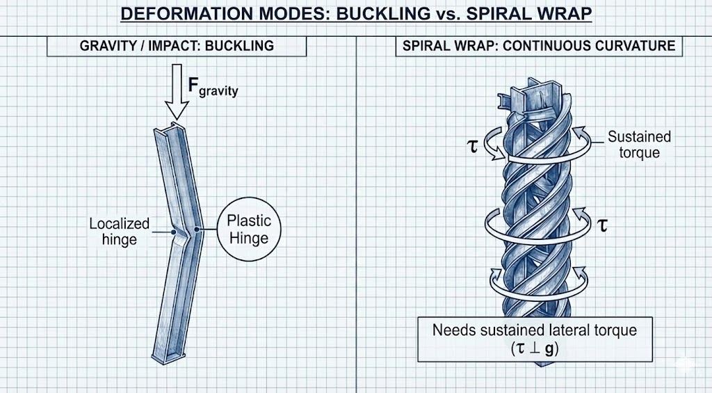
Baseline expectation (impact + collapse interactions): loads are generally impulsive and intermittent, tending to produce localized hinges, kinks, connection tears, and local buckles.
-
Observed phenotype (continuous curvature / tight wraps): smooth, near-constant-radius curvature over length implies distributed bending and/or a sustained moment history (continuous or many-cycle loading) rather than a single localized impulse.
-
Audit constraint: If the morphology is a tight spiral/roll, the explanation must supply a plausible moment/torque history (application geometry, restraint, duration/cycles) capable of producing continuous curvature.
Penetration / "projectile vs target" check:
In high-energy contact between similar steels and composite targets (steel/concrete/asphalt), energy typically partitions into plastic deformation in both bodies unless strong constraint/support conditions or contact geometry concentrate damage in one side.
- Audit discriminator: Claims of “target catastrophically failed while the steel member remained comparatively straight” must specify constraint/support/contact geometry (or an asserted transient reduction in target cohesion) that yields the observed asymmetry.
3. DATA CURATION & ANALYSIS
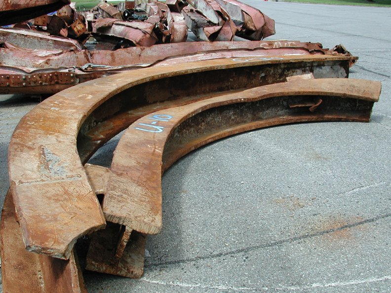
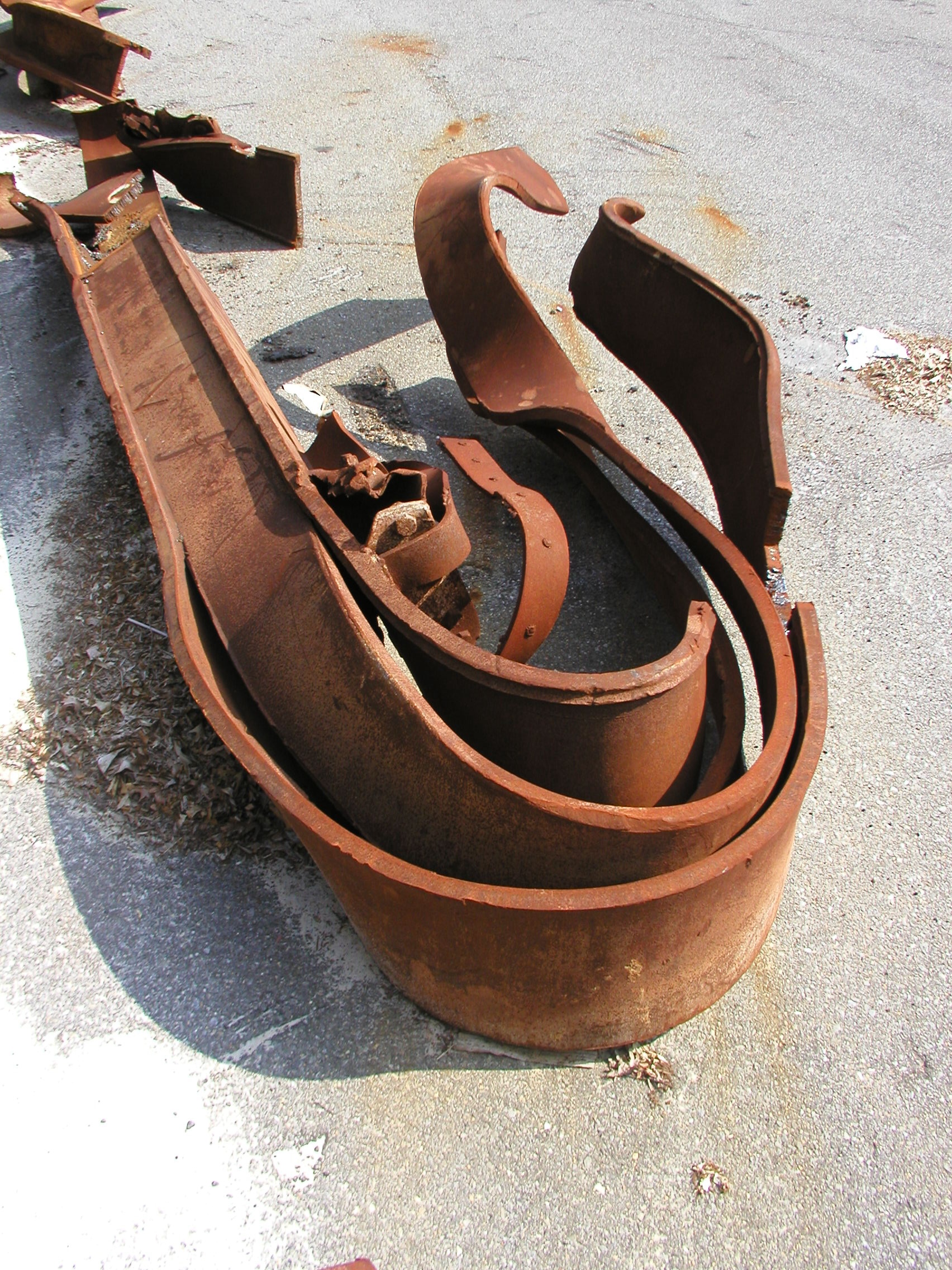
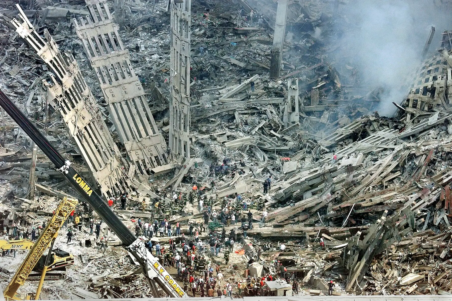
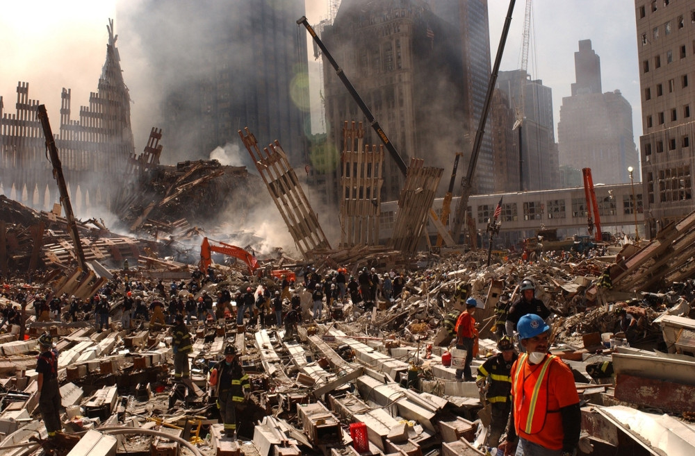
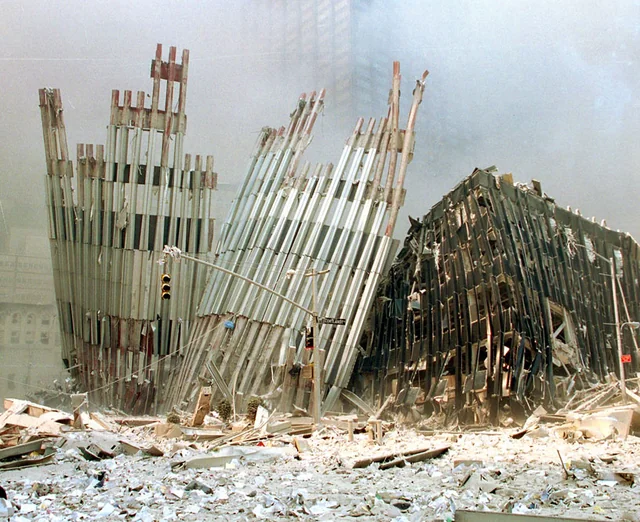
EVIDENCE FILE A: Cylindrical Plastic Wrapping
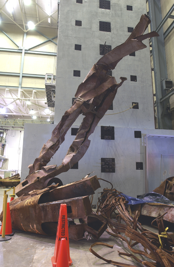
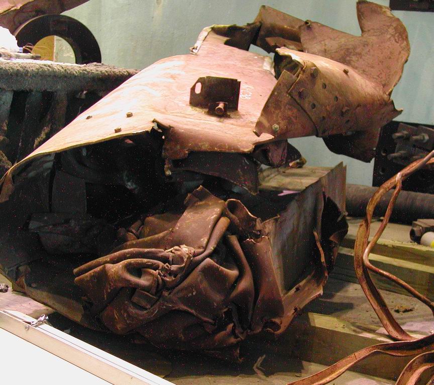
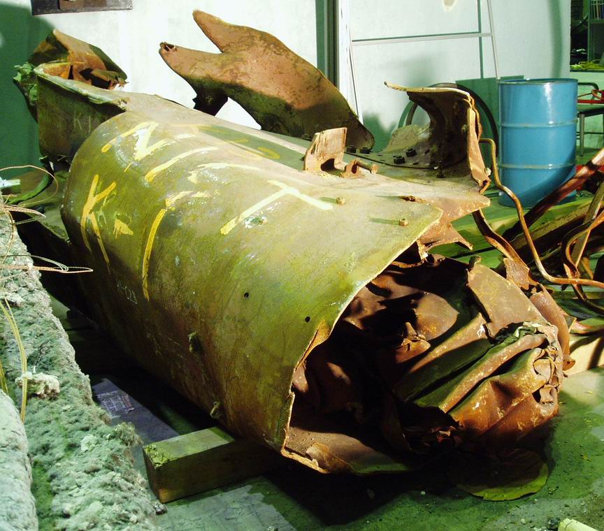
- Visual Data: Perimeter column assemblies (three columns + spandrel plates) are found wrapped around themselves in tight spirals. The spandrels exhibit Concentric Helical Winding around the column axis, demonstrating Coaxial Spandrel Deformation. The curvature is continuous and smooth ($\(r \approx \text{constant}\)$), lacking the sharp angular kinks associated with compressive buckling.
- The Standard Model Defense: "Eccentric impact" or "Peel and Fold" mechanisms.
- Boundary Condition Violation:
- Hinge discriminator: Impacts commonly create localized hinges/kinks. A "smooth roll" implies distributed curvature (many distributed yielding regions) rather than a small number of hinge points.
Moment-history gap: Gravity supplies a dominant downward drive; producing a tight spiral wrap requires a sustained or repeatedly applied lateral moment/torque history with a consistent wrap geometry (constraint/guide path), not merely generic downward loading. - Mechanism: The geometry functions as a boundary condition supporting athermal plasticity plus distributed body-force / field-gradient coupling capable of imposing a wrap-like moment history; Lorentz/eddy-current body forces are secondary where conductive-loop geometry is applicable.
- Hinge discriminator: Impacts commonly create localized hinges/kinks. A "smooth roll" implies distributed curvature (many distributed yielding regions) rather than a small number of hinge points.
- Classification: Athermal Plasticity / Coherent Field-Gradient Torque (Interferometric Node Coupling).
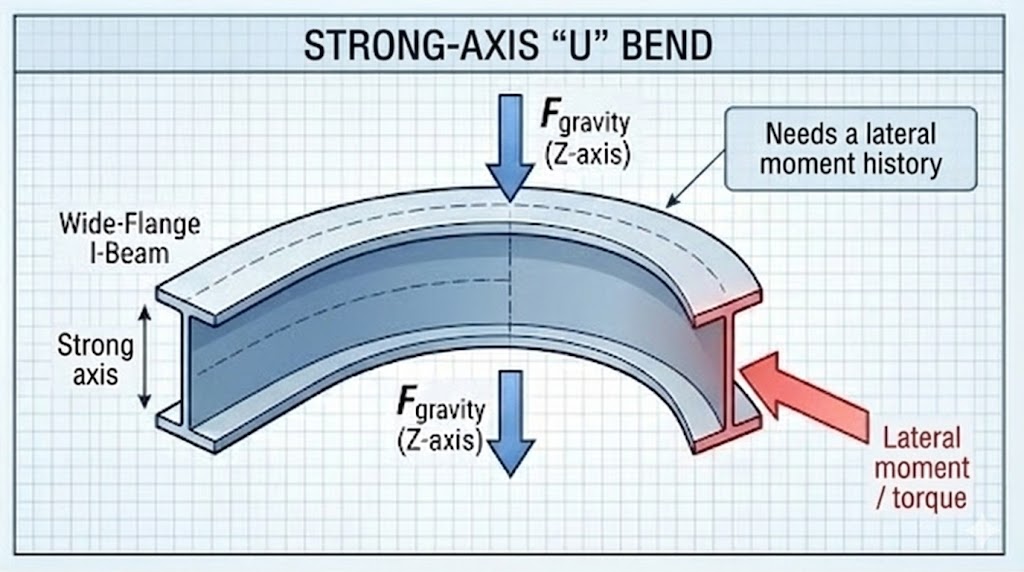
EVIDENCE FILE B: Orthogonal Axis Deformation ("The Wrong Axis")
- Visual Data: Heavy I-beams are bent into smooth semicircles ("U" shapes) around their Vertical Axis (The Strong Axis).
- The Standard Model Defense: "Pinned ends with lateral debris impact."
- Boundary Condition Violation:
- Work / geometry: Strong-axis bending to a smooth “U” shape implies large distributed bending work over length.
- Smoothness discriminator: A single-point impact of sufficient magnitude would often leave local web/connection damage near the contact/fulcrum. A smooth bend with limited local damage supports distributed loading (multiple contacts/restraints or a body-force–like coupling) over a single localized strike.
- Classification: Volumetric Body-Force Torque (Field-Gradient Coupling) / Orthogonal-Axis Deformation; secondary Lorentz effects where conductive loops dominate.
EVIDENCE FILE C: Differential Strain
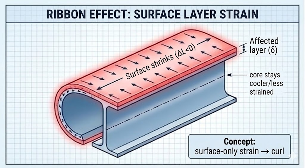
- Visual Data: A monolithic steel column exhibits a smooth, upward curl along its length, identical to a bimetallic strip or a ribbon curled by scissors.
- The Standard Model Defense: "Residual Stress release" or "Differential Fire Heating."
- Boundary Condition Violation:
- The Scale Problem: Thermal warping creates irregular, catenary sags. This curl is tight and uniform.
- Material / strain requirement: A smooth curl in a monolithic member implies differential strain through thickness or across the section (possible causes include thermal gradients, residual stress release, phase/oxide strain, or surface-layer–dominated effects).
- Audit discriminator: If macro thermal asymmetry is not evident, the report carries surface-layer / skin-effect–like coupling as the leading pathway within this dossier, while acknowledging non-field alternatives require metallography to bound.
- Classification: Differential Skin Stress / Field-Gradient Stress.
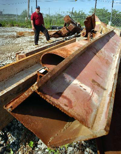
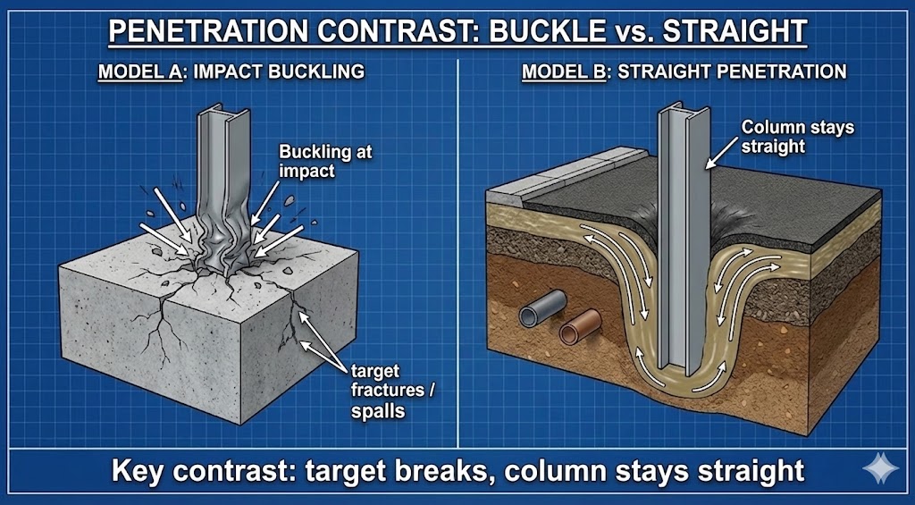
EVIDENCE FILE D: Survival of Projectiles
- Visual Data: Sections of the perimeter wall are found stabbed vertically into the street and adjacent buildings. These sections remain perfectly straight and unbuckled, despite the immense impact force required to penetrate concrete/asphalt.
- The Standard Model Defense: "Dynamic penetration physics."
- Boundary Condition Violation:
- Penetration audit check: Deep penetration with limited projectile buckling can occur under certain constraint/support and contact-geometry conditions; however, the burden shifts to specifying that geometry/constraint when the projectile remains notably straight while the target catastrophically fails.
- The Paradox: The "Target" (Street/Building) shattered; the "Projectile" (Column) remained elastic (Straight).
- Discriminator: If the target shows disproportionate loss while the projectile remains comparatively straight, the account should specify the constraint/impact geometry (or, as a candidate, a transient reduction in target cohesion) that produces the observed asymmetry.
- Classification: Impedance Matching / Target Softening.
4. CORROBORATING BIO-TELEMETRY & SENSORY DATA
All descriptive inputs for this record are morphological characterizations of static physical evidence and have been fully integrated into Section 3: Data Curation. No independent biological transducer telemetry (witness accounts) is available for this specific vector.
5. MECHANISMS OF NON-THERMAL FAILURE
Phenomenon: Cylindrical Plastic Wrapping $\(\rightarrow\)$ Mechanism: Coherent Field-Gradient Torque (Interferometric Node Coupling). The field applies distributed torque to the assembly while the yield strength is suppressed; eddy-current/Lorentz effects may be secondary in conductive loops.
Phenomenon: Transient Shear Modulus Reduction $\(\rightarrow\)$ Mechanism: Athermal Plasticity (The Blaha Effect). Ultrasonic or high-frequency electromagnetic resonance unpins dislocations in the crystal lattice, reducing yield strength near zero without melting.
Phenomenon: Bending Around Vertical Axis $\(\rightarrow\)$ Mechanism: Field-Gradient Torque. Lateral gradients apply torque perpendicular to gravity within the node geometry.
Phenomenon: Differential Laminar Strain $\(\rightarrow\)$ Mechanism: Differential Skin Stress. High-frequency skin effects heat or contract only the outer surface layer, causing the beam to curl away from the stress.
6. MICROSCOPY PROTOCOL
Objective: Distinguish Thermal Creep from Athermal Plasticity.
TEST A: Recrystallization / texture check (hot vs athermal flow)
Sample: High-curvature region of a rolled/wrapped member.
- Thermal-hot deformation prediction: evidence of recrystallization / equiaxed grains, oxidation/scale consistent with high temperature exposure.
- Athermal / low-temperature flow candidate: strongly elongated grains / deformation texture with limited recrystallization.
TEST B: Microhardness mapping (work-hardening discriminator)
Objective: Determine whether extreme curvature corresponds to expected work hardening.
- Conventional cold bend prediction: significant hardness increase in the high-strain zone (relative to undeformed stock).
- Athermal-softening candidate: smaller-than-expected hardness increase for the observed strain (requires careful control comparison to base material and heat history).
7. SYNTHESIS: The Spatially-Constrained Interferometric Event (SCIE) Classification Protocol
Thermodynamic Gap: The energy required to plastically deform massive steel beams into tight spirals ( $\(E_{plastic}\)$) without cracking or fracturing exceeds the available gravitational energy ( $\(U_g\)$) and violates the expected failure mode (buckling). The absence of heat-cracking confirms the plasticity was athermal.
Circuit Gap: The "Model B" (Interferometric Coupling) hypothesis explains the cylindrical geometry (consistent with coherent field geometry / node-constrained torque paths) and explains the “wrong axis” curvature as an outcome of distributed coupling / body-force–like loading (with Lorentz/eddy-current forces secondary where conductive-loop geometry is demonstrated), which the Standard Model (gravity) cannot generate.
The Classification:
- Rule A (Attributes): The event demonstrates Geometric Flux Constraint (cylindrical rolling), Selective Coupling (steel affected), and Systemic Circuit Integration (entire assemblies acting as conductive loops).
- Rule B (Justification): Within the mechanism classes evaluated in this dossier, a SCIE-class explanation is favored because it can accommodate the reported non-axial curvature/rolling morphology via field-mediated torque/gradient effects and temporary yield-strength suppression (athermal plasticity), with node/anti-node localization used as the geometric routing hypothesis under the stated assumptions, without requiring an ad hoc departure from an axial-buckling/impact-only deformation pathway.