Plastic Deformation and Non-Axial Curvature in Structural Steel
1. ABSTRACT
Standard Model Expectation: In gravity-driven structural failure of A36 steel, dominant outcomes typically include local/global buckling, plastic hinge formation, connection failure, and tearing, with deformation concentrated at hinge/connection regions under combined axial and lateral demands.
Empirical Contradiction: Forensic photography documents massive structural assemblies (perimeter columns and spandrels) rolled up into tight cylindrical geometries. Deformation occurs smoothly along the entire length rather than at discrete hinge points. Furthermore, I-beams exhibit extreme curvature around their vertical axis (the strong axis), a vector for which no gravitational load path exists.
Audit Objective: To determine if gravitational potential energy ( $\(U_g\)$) and mechanical impact forces are sufficient to explain the “rolled” morphology and orthogonal deformation vectors. This report also treats the deformation as a targeted stress-test of the one-dimensional collapse abstractions commonly used to defend Model A (e.g., crush-down/crush-up accounting): those models may bound vertical energy flow, but they do not by themselves provide the sustained non-axial moment/torque histories implied by smooth helical/ribbon curvature.
Audit Rule(s): Audit Rule 4 (Impulse-Momentum Constraint) where deformation implies sustained/large impulse or torque histories. Supporting: Audit Rule 2 (The Fourier/Joule Constraint) where localized, non-fire coupling is carried as a candidate to enable yield-strength suppression without bulk thermal equilibration.
2. CONTROL PARAMETERS
Thermodynamic / Mechanics Definition:
We treat the deformation as a work / plastic-dissipation audit. Relevant work measures include torsion and bending:
$\(W_{\text{torsion}}=\int \tau\, d\theta,\qquad W_{\text{bend}}=\int M\, d\kappa\)$ (or $\(\int M\, d\theta\)$ along the bent span).
Here $\(\tau\)$ denotes torque (not shear stress).
Distributed-curvature discriminator (rolling / smooth wraps):
-
Baseline expectation (impact + collapse interactions): loads are generally impulsive and intermittent, tending to produce localized hinges, kinks, connection tears, and local buckles.
-
Observed phenotype (continuous curvature / tight wraps): smooth, near-constant-radius curvature over length implies distributed bending and/or a sustained moment history (continuous or many-cycle loading) rather than a single localized impulse.
-
Audit constraint: If the morphology is a tight spiral/roll, the explanation must supply a plausible moment/torque history (application geometry, restraint, duration/cycles) capable of producing continuous curvature.
Penetration / "projectile vs target" check:
In high-energy contact between similar steels and composite targets (steel/concrete/asphalt), energy typically partitions into plastic deformation in both bodies unless strong constraint/support conditions or contact geometry concentrate damage in one side.
- Audit discriminator: Claims of “target catastrophically failed while the steel member remained comparatively straight” must specify constraint/support/contact geometry (or an asserted transient reduction in target cohesion) that yields the observed asymmetry.
3. DATA CURATION & ANALYSIS
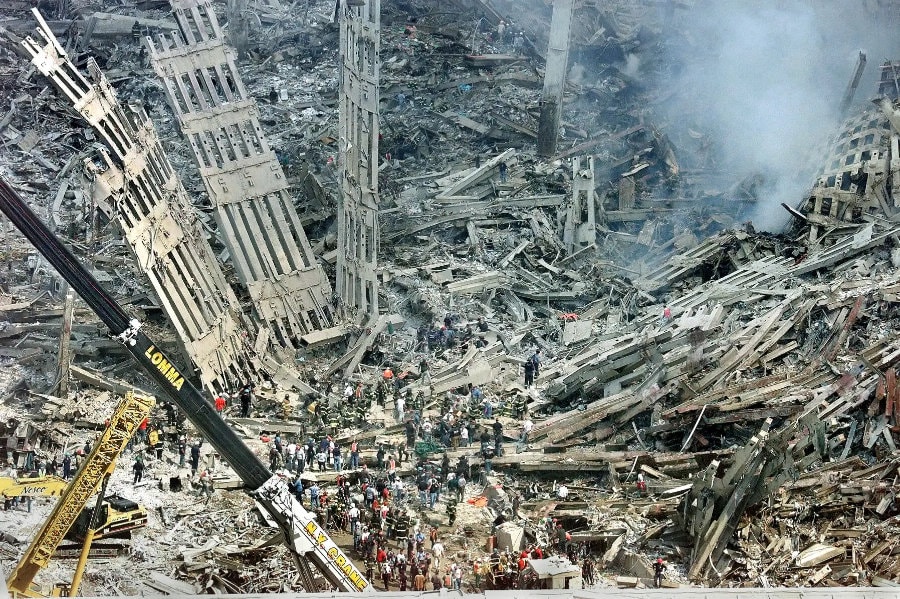
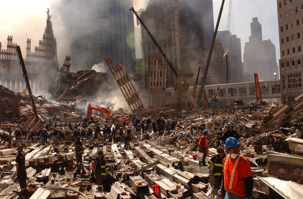
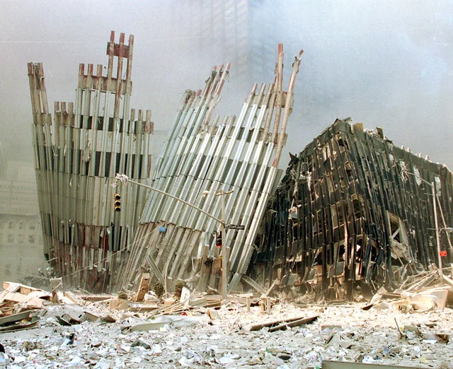
EVIDENCE FILE A: Cylindrical Plastic Wrapping
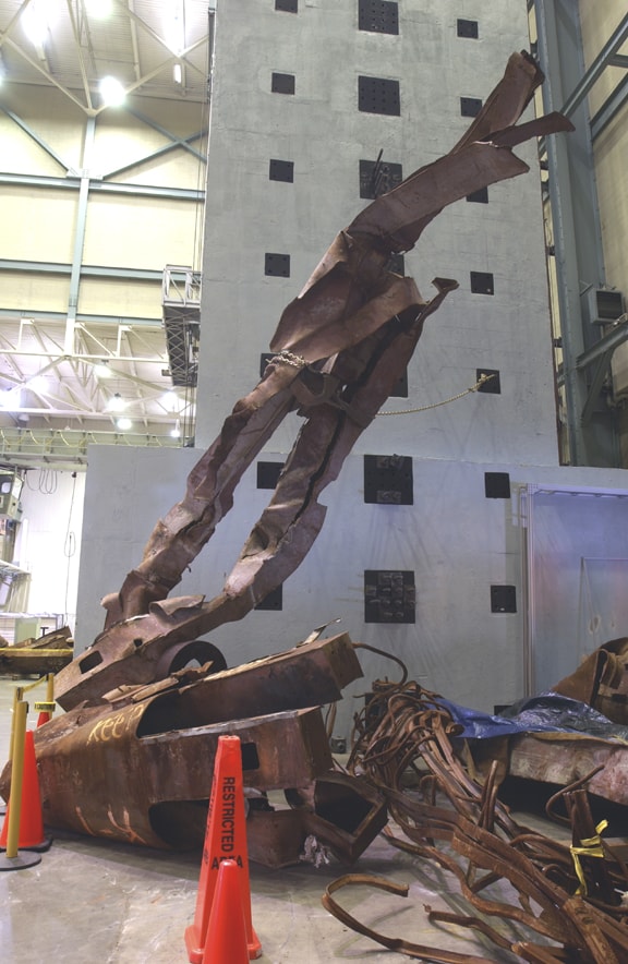
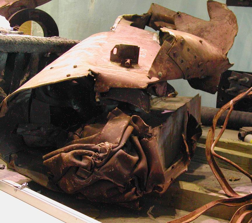
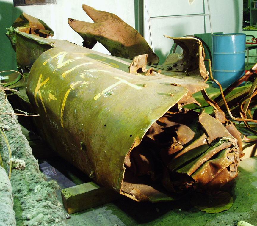
Figures 35-37. WTC perimeter column assemblies wrapped into tight cylindrical spirals with smooth continuous curvature, demonstrating helical winding and coaxial spandrel deformation inconsistent with gravity collapse.
- Visual Data: Perimeter column assemblies (three columns + spandrel plates) are found wrapped around themselves in tight spirals. The spandrels exhibit Concentric Helical Winding around the column axis, demonstrating Coaxial Spandrel Deformation. The curvature is continuous and smooth ($\(r \approx \text{constant}\)$), lacking the sharp angular kinks associated with compressive buckling.
- The Standard Model Defense: "Eccentric impact" or "Peel and Fold" mechanisms.
- Boundary Condition Violation:
- Hinge discriminator: Impacts commonly create localized hinges/kinks. A "smooth roll" implies distributed curvature (many distributed yielding regions) rather than a small number of hinge points.
Moment-history gap: Gravity supplies a dominant downward drive; producing a tight spiral wrap requires a sustained or repeatedly applied lateral moment/torque history with a consistent wrap geometry (constraint/guide path), not merely generic downward loading. - Mechanism: The geometry functions as a boundary condition supporting athermal plasticity plus distributed body-force / field-gradient coupling capable of imposing a wrap-like moment history; Lorentz/eddy-current body forces are secondary where conductive-loop geometry is applicable.
- Hinge discriminator: Impacts commonly create localized hinges/kinks. A "smooth roll" implies distributed curvature (many distributed yielding regions) rather than a small number of hinge points.
- Classification: Athermal Plasticity / Coherent Field-Gradient Torque (Interferometric Node Coupling).
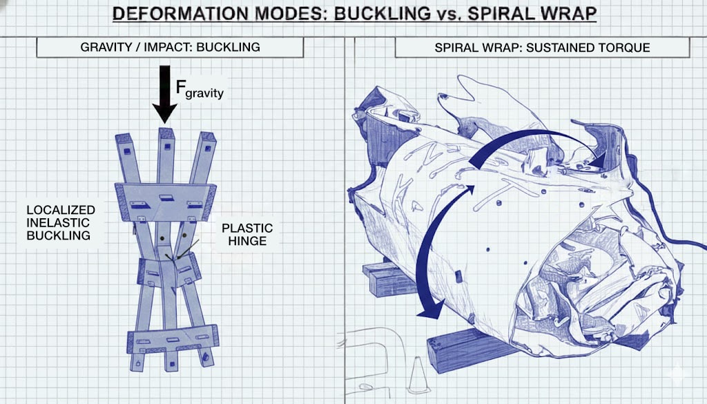
Diagram 16. Deformation modes: buckling (localized hinge) vs spiral wrap (sustained torque, continuous curvature)—smooth roll implies moment/torque history.
EVIDENCE FILE B: Orthogonal Axis Deformation ("The Wrong Axis")
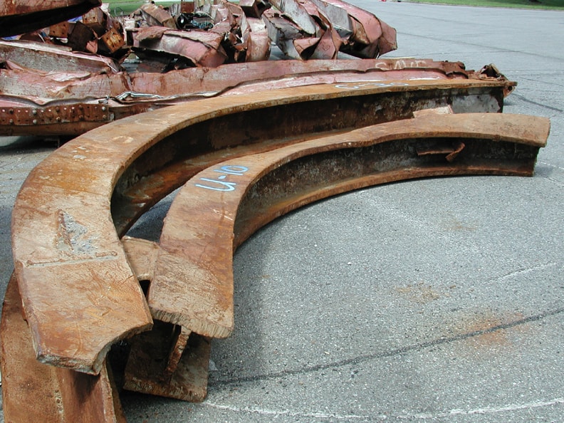
Figure 38. Heavy I-beams bent into smooth semicircles around their vertical strong axis, demonstrating orthogonal-axis deformation inconsistent with gravitational overload. Image by NIST.
- Visual Data: Heavy I-beams are bent into smooth semicircles ("U" shapes) around their Vertical Axis (The Strong Axis).
- The Standard Model Defense: "Pinned ends with lateral debris impact."
- Boundary Condition Violation:
- Work / geometry: Strong-axis bending to a smooth “U” shape implies large distributed bending work over length.
- Smoothness discriminator: A single-point impact of sufficient magnitude would often leave local web/connection damage near the contact/fulcrum. A smooth bend with limited local damage supports distributed loading (multiple contacts/restraints or a body-force–like coupling) over a single localized strike.
- Classification: Volumetric Body-Force Torque (Field-Gradient Coupling) / Orthogonal-Axis Deformation; secondary Lorentz effects where conductive loops dominate.
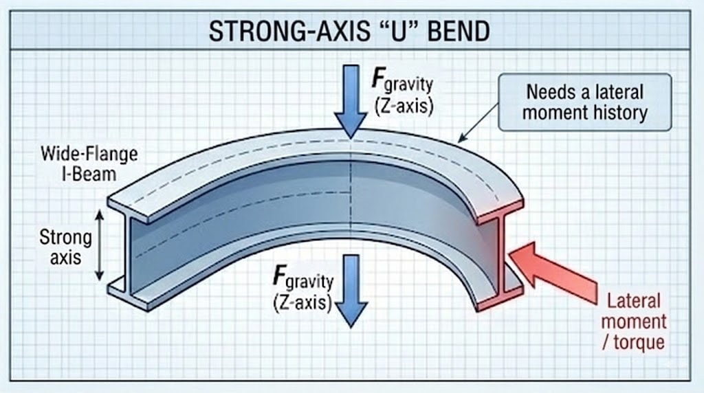
Diagram 17. Strong-axis U bend: bending around vertical axis with lateral moment/torque—requires lateral moment history.
EVIDENCE FILE C: Differential Strain
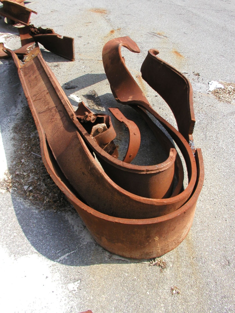
Figures 39-40. WTC I-beams and perimeter columns showing smooth curl and differential strain, demonstrating orthogonal-axis deformation inconsistent with thermal warping.
- Visual Data: A monolithic steel column exhibits a smooth, upward curl along its length, identical to a bimetallic strip or a ribbon curled by scissors.
- The Standard Model Defense: "Residual Stress release" or "Differential Fire Heating."
- Boundary Condition Violation:
- The Scale Problem: Thermal warping creates irregular, catenary sags. This curl is tight and uniform.
- Material / strain requirement: A smooth curl in a monolithic member implies differential strain through thickness or across the section (possible causes include thermal gradients, residual stress release, phase/oxide strain, or surface-layer–dominated effects).
- Audit discriminator: If macro thermal asymmetry is not evident, the report carries surface-layer / skin-effect–like coupling as the leading pathway within this dossier, while acknowledging non-field alternatives require metallography to bound.
- Classification: Differential Skin Stress / Field-Gradient Stress.
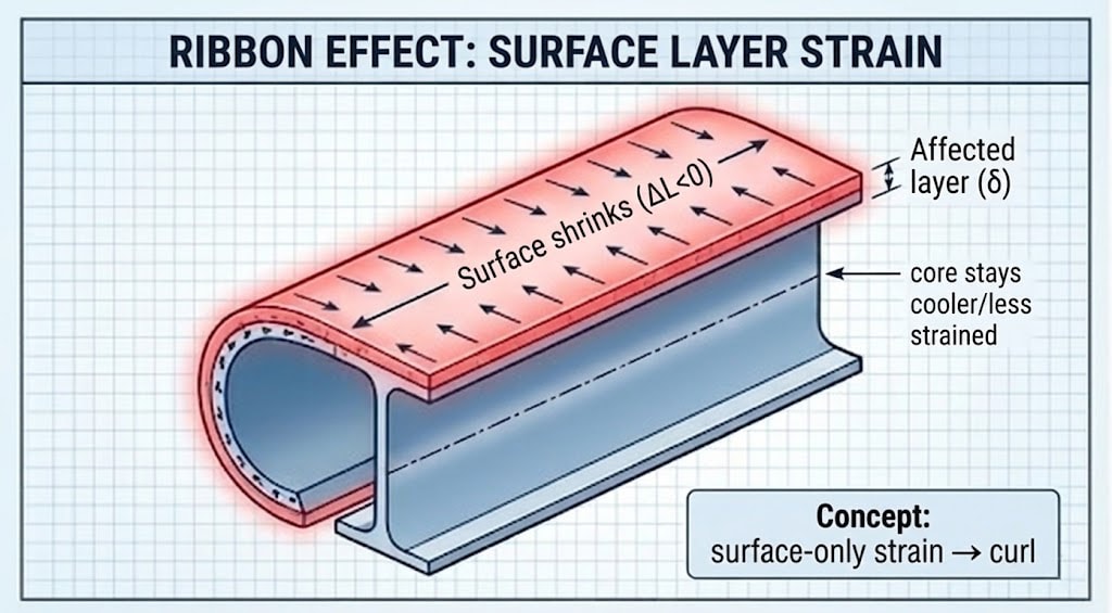
Diagram 18. Ribbon effect: surface-layer strain (shrinkage) with core less strained—surface-only strain → curl.
EVIDENCE FILE D: Survival of Projectiles
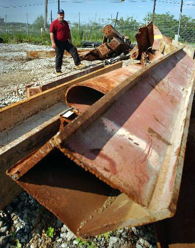
Figures 41-43. WTC perimeter column panels and window panels stabbed into streets, remaining straight and unbuckled while targets catastrophically failed, demonstrating impedance matching.
- Visual Data: Sections of the perimeter wall are found stabbed vertically into the street and adjacent buildings. These sections remain notably straight with limited buckling despite deep penetration into concrete/asphalt.
- The Standard Model Defense: "Dynamic penetration physics."
- Boundary Condition Violation (audit framing):
- Penetration audit check: Deep penetration with limited projectile buckling can occur under specific constraint/support and contact-geometry conditions; the burden shifts to specifying that geometry/constraint when the projectile remains notably straight while the target catastrophically fails.
- Asymmetry: The target (street/building) shows disproportionate failure while the projectile remains comparatively straight.
- Discriminator: The account should specify the constraint/impact geometry (or, as a candidate, a transient reduction in target cohesion) that produces the observed asymmetry.
- Classification (candidate): Impedance asymmetry / target-softening candidate (mechanism carried pending geometry/constraint specification).
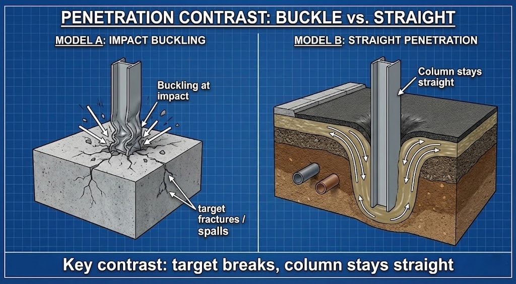
Diagram 19. Penetration contrast: buckle (column deforms, target fractures) vs straight penetration (column stays straight, target displaced).
4. CORROBORATING BIO-TELEMETRY & SENSORY DATA
All descriptive inputs for this record are morphological characterizations of static physical evidence and have been fully integrated into Section 3: Data Curation. No independent witness telemetry is used for this specific vector.
5. MECHANISMS OF NON-THERMAL FAILURE
Phenomenon: Cylindrical Plastic Wrapping $\(\rightarrow\)$ Mechanism: Coherent Field-Gradient Torque (Interferometric Node Coupling). The field applies distributed torque to the assembly while the yield strength is suppressed; eddy-current/Lorentz effects may be secondary in conductive loops.
Phenomenon: Transient Shear Modulus Reduction $\(\rightarrow\)$ Mechanism: Athermal Plasticity (The Blaha Effect). Ultrasonic or high-frequency electromagnetic resonance unpins dislocations in the crystal lattice, reducing yield strength near zero without melting.
Phenomenon: Bending Around Vertical Axis $\(\rightarrow\)$ Mechanism: Field-Gradient Torque. Lateral gradients apply torque perpendicular to gravity within the node geometry.
Phenomenon: Differential Laminar Strain $\(\rightarrow\)$ Mechanism: Differential Skin Stress. High-frequency skin effects heat or contract only the outer surface layer, causing the beam to curl away from the stress.
6. MICROSCOPY PROTOCOL
Objective: Distinguish Thermal Creep from Athermal Plasticity.
TEST A: Recrystallization / texture check (hot vs athermal flow)
Sample: High-curvature region of a rolled/wrapped member.
- Thermal-hot deformation prediction: evidence of recrystallization / equiaxed grains, oxidation/scale consistent with high temperature exposure.
- Athermal / low-temperature flow candidate: strongly elongated grains / deformation texture with limited recrystallization.
TEST B: Microhardness mapping (work-hardening discriminator)
Objective: Determine whether extreme curvature corresponds to expected work hardening.
- Conventional cold bend prediction: significant hardness increase in the high-strain zone (relative to undeformed stock).
- Athermal-softening candidate: smaller-than-expected hardness increase for the observed strain (requires careful control comparison to base material and heat history).
7. SYNTHESIS: The Spatially-Constrained Interferometric Event (SCIE) Classification Protocol
Impulse-Momentum Gap (Audit Rule 4; work/torque history): The observed deformation morphology cannot be reconciled with a purely impact/buckling-dominated failure pathway without specifying an adequate sustained moment/torque history; gravity supplies a dominant downward drive and cannot generate the lateral moment history required for tight spiral wrapping.
Discriminator framing (local veto): Where the reported steel morphologies are correctly characterized as broad smooth non-axial curvature and torsion (smooth helical/ribbon curls) rather than hinge-localized kinks/tears/fractures, they function as a high-specificity discriminator: Model A must supply a concrete loading/constraint history that naturally produces continuous curvature while also matching the expected collateral signatures. If it cannot, Model A fails this constraint under the stated boundary assumptions.
Model A escape-hatch checklist (what must be specified, not hand-waved):
- Constraint/guide geometry: What guide path, restraint, or boundary condition forces a consistent wrap radius and sustained torque history (as opposed to a one-off impulse)?
- Localization signatures: Where are the expected hinge points, connection tears, and kink localization that ordinarily accompany severe plastic deformation under impact/buckling?
- Thermal history: If fire/thermal gradients are invoked, what metallographic signatures (through-thickness grain growth, recrystallization, oxide gradients) demonstrate a bulk-soak pathway consistent with the claimed morphology?
- Axis-of-bending mechanism: For “wrong-axis” curvature, what specific contact/loading configuration supplies the required moment vector in a gravity-dominated environment?
See: APPENDIX — Model A Steelman & Failure Modes.
For the focused mechanics note that situates the beam simulation against 1D collapse abstractions, see: APPENDIX — Beam Mechanics (Morphology Discriminator).
The work required to plastically deform massive steel beams into tight spirals ($\(E_{plastic}\)$ ) without cracking or fracturing may exceed the available gravitational energy ($\(U_g\)$) under the stated assumptions; whether $\(E_{plastic} > U_g\)$ depends on participation and strain distribution. If $\(E_{plastic} > U_g\)$, the system requires additional energy input beyond gravitational potential. The absence of obvious thermal-damage signatures is treated as consistent with athermal (bulk) plasticity, absent additional assumptions.
Circuit Gap: The "Model B" (Interferometric Coupling) hypothesis explains the cylindrical geometry (consistent with coherent field geometry / node-constrained torque paths) and explains the “wrong axis” curvature as an outcome of distributed coupling / body-force–like loading (with Lorentz/eddy-current forces secondary where conductive-loop geometry is demonstrated), which the Standard Model (gravity) cannot generate.
Quantitative demonstration (supporting illustration): A simple mechanics simulation contrasting hinge-localized loading vs distributed field-like loading is provided as a visualization aid (not a substitute for metallography). The figure is included below; the source script is available on request to good-faith reviewers.
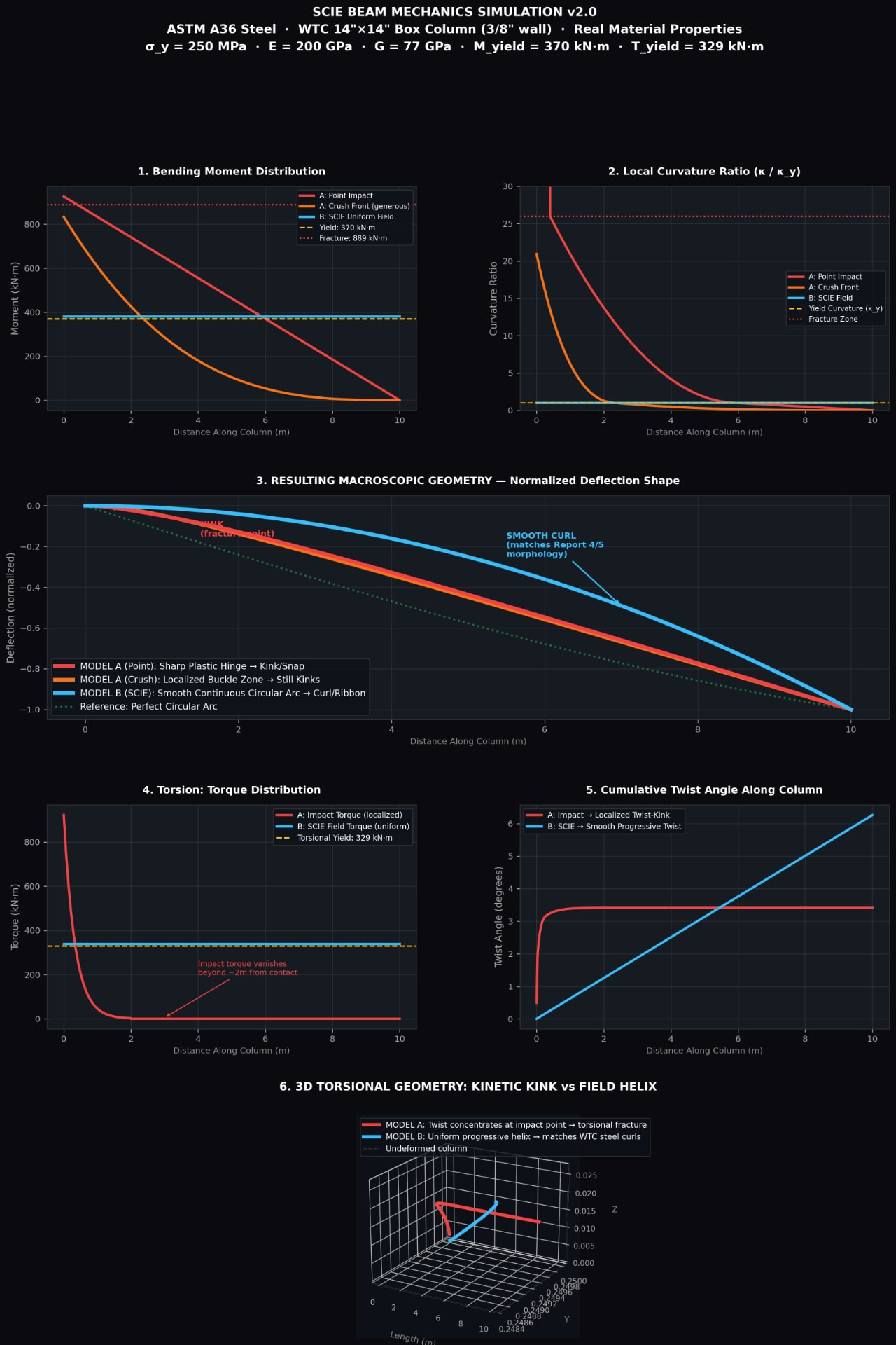
For a short, self-contained note that situates this simulation in the Model A vs SCIE comparison (and clarifies what it does and does not claim), see the appendix: APPENDIX — Beam Mechanics (Morphology Discriminator).
The Classification:
- SCIE Attributes: The event exhibits Geometric Flux Constraint (cylindrical rolling), Selective Coupling (steel affected), and Systemic Circuit Integration (entire assemblies acting as conductive loops).
- SCIE Justification: Within the mechanism classes evaluated in this dossier, a SCIE-class explanation is favored because it can accommodate the reported non-axial curvature/rolling morphology via field-mediated torque/gradient effects and temporary yield-strength suppression (athermal plasticity), with node/anti-node localization used as the geometric routing hypothesis under the stated assumptions, without requiring an ad hoc departure from an axial-buckling/impact-only deformation pathway.