Volumetric Mass Deficit and Bounded Vertical Void Analysis
1. ABSTRACT
Standard Model Expectation: In a gravity-driven collapse or kinetic impact event, adjacent-structure damage is expected to appear as irregular crushing, shattering, and debris accumulation that closes locally as rubble infill, surrounding piles, subgrade accumulation, exported fines, or documented removal. Deep punch-through paths ordinarily leave a choke term at or near the terminus unless the material is later cleared or redistributed.
Empirical Contradiction / Macro-Architecture Problem: WTC 6 presents a scalloped cluster of bounded vertical voids / aperture openings cutting through multiple reinforced-concrete floors with little visible terminus debris. WTC 4 presents a large, bounded planar truncation in which the main body is absent while a thin wing remains. Liberty Street contributes a secondary margin clue: localized deformation that reads more like softening at the edge of a bounded subtraction problem than ordinary top-down impact damage.
Audit Objective: To evaluate whether impact/collapse plus cleanup can close both the geometry and the local inventory, or whether the record is better carried as bounded excavation / truncation geometry with a mass-disposition burden not closed by ordinary choke rubble and, secondarily, localized margin softening.
Audit Rule(s): Audit Rule 3 (The Geometric Flux Constraint) for bounded aperture-like and planar-cut geometry. Supporting: Audit Rule 1 (The Comminution Limit) where the missing inventory must be closed by export, subgrade capture, redistribution, or documented removal.
Model A steelman (and the discriminator)
- Steelman: Model A closes this report only if one documented impact/removal history explains the bounded footprints, the observed terminus/infill state, and the imaging timeline without fragmenting the answer into punch-through here, cleanup there, and perspective elsewhere.
- Discriminator: This report's discriminator is the conjunction of bounded geometry (scalloped vertical void / aperture complex; planar truncation) and the time-of-imaging inventory problem (limited visible terminus debris / unresolved expected infill) under the stated assumptions.
- What Model A must show: a constrained impact/removal history and a local inventory account consistent with the documented imaging timeline, the observed boundary geometry, the terminus state, and the collateral deformation at the margins.
See: APPENDIX — Model A Steelman & Failure Modes (comminution/export closure: C1).
2. CONTROL PARAMETERS
A. Inventory Closure
We treat the affected structures and immediate mapped surroundings as a mass-inventory audit over a defined control volume.
If a large internal volume is described as "empty," the audit question is where that mass is observed or registered within those terms rather than asserting a literal violation of mass conservation.
B. Penetration / Excavation Mechanics
Standard expectation: A sustained through-floor penetration pathway ordinarily leaves substantial rubble along the path or a choke term at lower levels unless the material is later removed or redistributed.
Impact work bound:
The burden is not just to make a hole. It is to do so with the documented boundary precision and with a local inventory state that does not simply resolve as piled comminuted debris at the terminus.
C. Boundary / Truncation Constraint
Standard expectation: Collapse and debris impact ordinarily yield irregular fracture geometry, uneven damage gradients, and mixed survival rather than stable bounded-aperture or planar cutoffs.
Geometry discriminator: If bounded geometry and an unresolved local inventory term co-occur, the carried architecture must supply:
- a structured footprint control for the affected volume
- a documented mass-disposition pathway if ordinary terminus rubble does not close the scene at the documented time of imaging
- where relevant, localized margin softening to explain the edge deformation without treating it as the primary driver
3. DATA CURATION & ANALYSIS
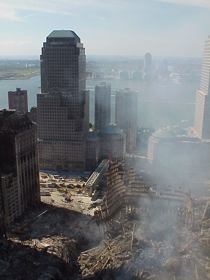
EVIDENCE FILE A: Bounded Vertical Void / Aperture Complex (WTC 6)
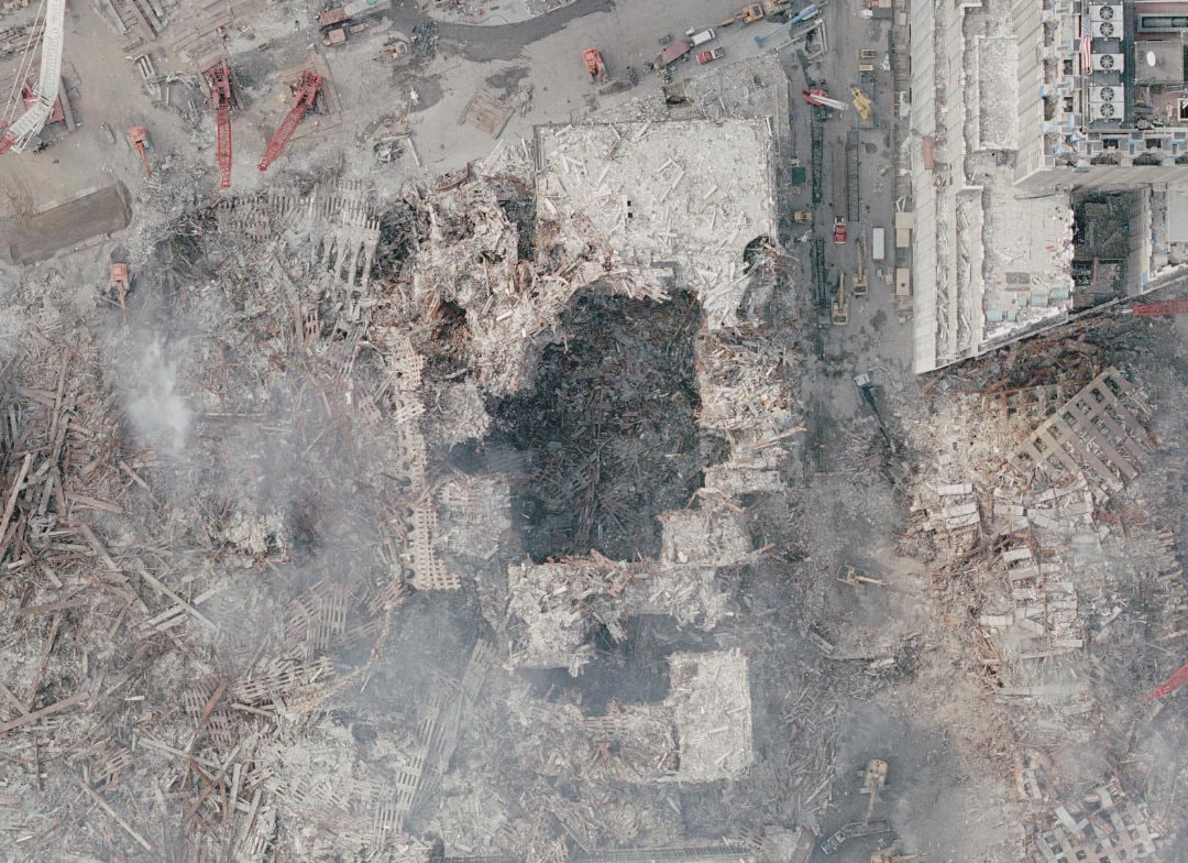
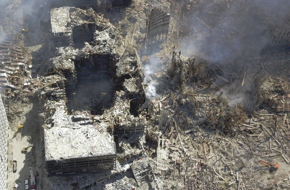
Figures 96-99. Aerial and interior views of WTC 5 and WTC 6 showing bounded vertical void / aperture openings cutting through multiple floors with limited visible debris accumulation.
- Observation: WTC 6 exhibits an irregular, scalloped cluster of bounded vertical void / aperture openings. Within that larger void-aperture complex, the NOAA image supports a ~25-30 m principal dark-core / sub-aperture lateral scale. The openings cut through multiple reinforced-concrete floors to the ground level. The interior is repeatedly described as largely empty, with little visible debris inside and no obvious pancaked floor stack at the terminus; responders described the "heart of the building" as gone. The border appears scalloped rather than jagged.
- Model A local path: one documented punch-through/removal history producing both the repeat-like / scalloped bounded footprint and the limited observed shaft infill / terminus debris at the relevant imaging stage. Generic references to washout, redistribution, or later cleanup do not close this scene.
- Architecture discriminator: The issue is not a hole by itself. It is the conjunction of a repeat-like / scalloped bounded footprint and limited visible terminus debris relative to the expected floor / roof rubble at the documented imaging stage. If the missing floor and roof mass is not present as shaft infill, commensurate subgrade accumulation, adjacent pile, or documented removal, then the local ledger does not close as an ordinary punch-through pathway.
- Architecture reading: This is carried as bounded vertical void / aperture geometry with a repeat-like footprint plus an unresolved local mass-disposition burden where ordinary choke rubble is not documented at the relevant stage. That is narrower than a settled driver claim, but stronger than a generic impact irregularity.
- Constraint judgment: Any macro-architecture carried forward from this report must explain both the footprint stability and the terminus/infill state. A collapse-only account that explains one while leaving the other open does not close this file.
Diagram 42. Impact penetration (rubble infill) vs bounded vertical void / aperture complex (limited visible infill, scalloped edge)—audit gap: where did the mass go?
EVIDENCE FILE B: The "Sliced" WTC 4 Anomaly
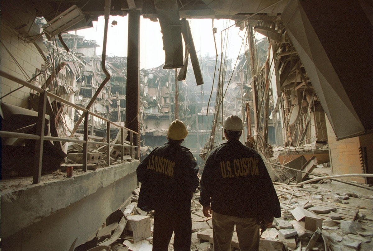
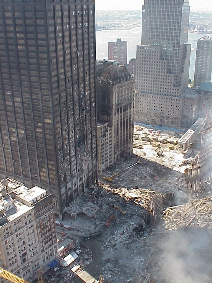
Figures 100-102. WTC4 showing a clean vertical planar cut separating near-total loss from adjacent preservation, demonstrating geometric precision inconsistent with debris-impact randomness under the stated assumptions.
- Observation: The main body of WTC 4 is absent while a thin wing remains standing with a clean, large-scale vertical cutoff between near-total loss and adjacent preservation.
- Model A local path: a specific impact/shielding history producing the stable planar cutoff under the actual geometry and damage sequence. Generic references to heterogeneous survival do not close this file.
- Architecture discriminator: Mechanical collapse and debris-impact damage are ordinarily irregular. They do not naturally predict a stable planar delineation between missing and preserved volume without a highly constrained impact geometry and shielding history that must itself be shown.
- Architecture reading: This is carried as bounded truncation geometry: a sharp footprint cutoff separating a removed volume from an adjacent preserved zone.
- Constraint judgment: Any macro-architecture carried forward from this report must explain why the geometry closes as a large-scale boundary rather than as ordinary irregular impact damage.
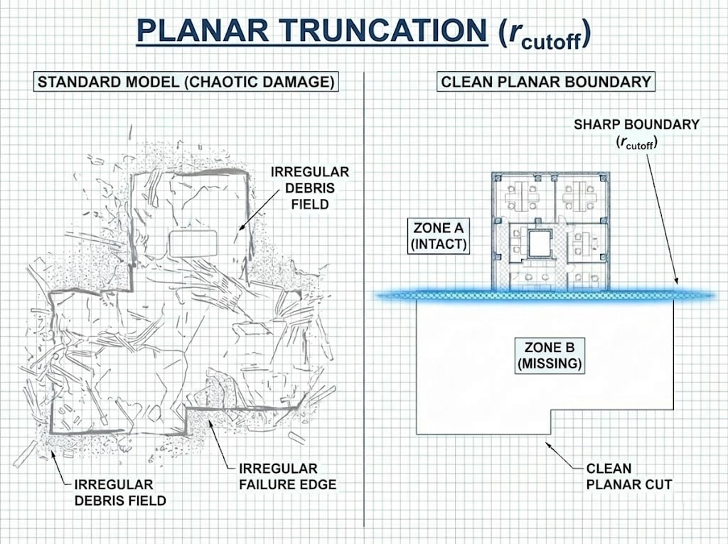
Diagram 43. Planar truncation \(r_{\mathrm{cutoff}}\): chaotic damage vs. clean planar boundary—sharp boundary between intact zone and missing zone.
EVIDENCE FILE C: Anomalous Deformation at Liberty Street
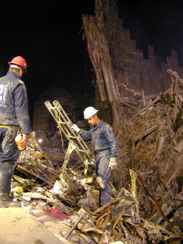
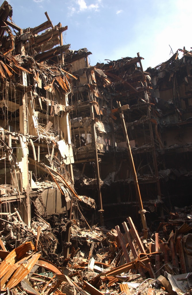
Figures 103-106. Liberty Street anomalies showing steel columns with sinusoidal deformation, shriveled beams, missing lower portions, and athermal plasticity, demonstrating anomalous deformation patterns inconsistent with gravity-driven collapse.
- Observation: Liberty Street shows deep local voiding, sinusoidal or "unfolded" column deformation, shriveled beam sections, and a beam end missing its lower portion while the upper portion remains.
- Model A local path: a bounded mechanical/thermal handling history reproducing the edge deformation and missing-lower-section asymmetry under documented scene conditions. Generic references to buckling, post-event handling, or heat-assisted softening do not close the edge file.
- Architecture discriminator: This is not the report's primary geometry line, but it matters at the boundary. Tight sinusoidal deformation without obvious fracture is difficult to square with ordinary impact buckling alone, and if the local scene lacks clear evidence of sustained high-temperature softening, purely thermal explanations remain under pressure.
- Architecture reading: Liberty Street is carried as a secondary margin clue: localized softening or distributed edge deformation at the boundary of the bounded subtraction problem rather than as an independent architecture proof.
- Constraint judgment: This file strengthens the edge condition of the report's geometry problem, but it remains secondary to the WTC 6 and WTC 4 geometry-and-inventory conjunction.
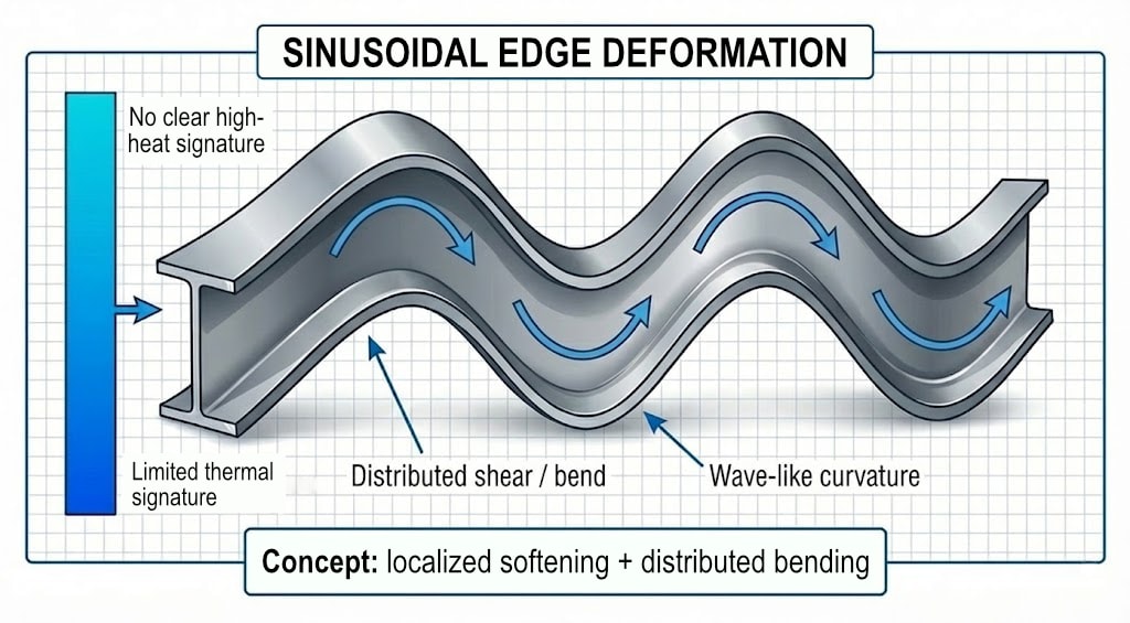
Diagram 44. Sinusoidal edge deformation: no clear high-heat signature; localized softening + distributed bending.
4. CORROBORATING LOCAL TELEMETRY AND SCENE CHECKS
Objective: carry only the local scene accounts that sharpen the inventory-timing question without turning witness material into a self-sufficient proof.
DATA SET A: WTC 6 Interior and Shaft-Terminus Accounts
WTC6-INT-01 (Emergency Services Unit)
- Observation: A responder described a "massive crater" extending vertically from the roof to the sub-level and emphasized how much of Building 6 was simply gone.
- Use in this report: This strengthens the time-of-imaging inventory problem. It supports the claim that the void was not merely a narrow penetration with an obvious interior choke term.
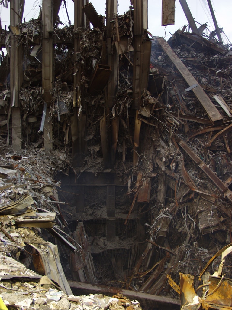
WTC6-TERM-02 (First Responder / Firefighter)
- Observation: A responder described a clean vertical aperture roughly sixty feet deep and explicitly noted that the "heart of the building" was gone, with no pancaked floors stacked at the base.
- Use in this report: This sharpens the terminus-level inventory issue raised in Evidence File A.
Cross-check: Taken together, these scene accounts strengthen the local geometry-and-inventory conjunction: a deep bounded void with limited visible terminus debris at the time of documentation and no obvious stacked floor mass at the base.
5. MACRO-ARCHITECTURE PICTURE
The strongest line in this report is not geometry alone and not sparse inventory alone. Either one by itself is easier to contest. The report carries the conjunction: bounded geometry plus unresolved terminus/infill inventory.
WTC 6 provides the vertical-void version of that conjunction. The openings do not read as ordinary chaotic punch-through if the footprint remains repeat-like while the expected rubble choke is not documented at the terminus. WTC 4 carries the same bounded-subtraction problem in planar form: a large removed volume closing as a sharp boundary rather than irregular impact loss. Liberty Street then contributes a secondary edge clue: if the bounded subtraction problem is real, the surrounding margin may show localized softening or distributed deformation rather than only ordinary impact shredding.
The core architecture elements carried forward from this report are:
- Bounded excavation / truncation geometry: the removed volume closes as a stable footprint problem rather than as generic irregular impact damage.
- Documented mass-disposition pathway beyond ordinary choke rubble: the missing mass does not simply resolve as terminus infill within the documented scene window.
The secondary carry-forward reading is:
- Localized margin softening: the Liberty Street deformation is carried as an edge condition of the bounded subtraction problem, not as a co-equal load-bearing geometry proof.
Even if the Liberty Street edge clue is set aside, the WTC 6 / WTC 4 conjunction still carries the report's main architecture burden.
This report does not yet specify the exact excavation driver, number of passes, field shape, or delivery path. It advances the architecture burden: if the geometry is bounded and ordinary local rubble closure remains undocumented, the reconstruction must supply both footprint control and a documented mass-disposition pathway.
6. ARCHITECTURE TEST PROTOCOL
Objective: distinguish irregular impact / collapse excavation from bounded removal geometry with unresolved local inventory closure.
TEST A: Aperture Wall Metrology and Embedment Check
- Sample zone: Scalloped aperture walls and surviving concrete / steel edges in the WTC 6 void / aperture zone.
- Standard expectation: shattered aggregate, torn fracture surfaces, angular irregularity, and foreign embedment consistent with blunt impact and crush-through.
- Architecture expectation: repeat-like edge morphology with low foreign embedment and less evidence of blunt impact shredding than a chaotic punch-through account would predict.
TEST B: Rebar Terminus and Floor-Edge Severing
- Sample zone: Severed reinforcement bars and floor-edge boundaries adjacent to the aperture / truncation zones.
- Standard expectation: necking, shear tearing, bent remnants, and stacked comminuted floor material consistent with impact and crush-down choke.
- Architecture expectation: abrupt severing or removal signatures with weaker plastic elongation than a straightforward crush-through account would predict, pending microscopy discriminators.
TEST C: Time-of-Imaging Inventory Reconciliation
- Sample zone: WTC 6 shaft terminus, adjacent piles, subgrade accumulation, mapped surroundings, and documented removal timeline.
- Standard expectation: the missing mass should close locally as infill, adjacent rubble, subgrade accumulation, or removal already documented before the relevant imaging window.
- Architecture expectation: if local closure remains unresolved at the documented time of imaging, the audit burden shifts to export, removal, or another documented mass-disposition pathway beyond ordinary choke rubble.
TEST D: Boundary Plane and Margin-Softening Reconstruction
- Sample zone: WTC 4 truncation boundary and Liberty Street edge deformation.
- Standard expectation: irregular impact margins, mixed survival, and thermal or mechanical damage gradients without a stable bounded cutoff.
- Architecture expectation: a bounded planar or aperture-like footprint with any margin softening concentrated at the edge of that footprint rather than distributed as generic chaotic damage.
7. MACRO-ARCHITECTURE JUDGMENT
- Macro-architecture result: The WTC 6 and WTC 4 record is best carried as a bounded excavation / truncation problem, not as ordinary impact-collapse damage that already closes locally.
- Strongest architecture line: The key conjunction is bounded geometry plus unresolved terminus/infill inventory. That is the report's main burden on the standard account.
- What this report advances: It advances a footprint-control problem and a mass-disposition problem together.
- Core architecture elements carried forward: bounded excavation / truncation geometry and a documented mass-disposition pathway beyond ordinary choke rubble.
- Secondary carry-forward reading: Liberty Street contributes localized margin softening as an edge clue, not as a self-sufficient architecture proof.
- Downstream primary completion work: The exact excavation driver, field shape, pass structure, and delivery path remain downstream primary completion work; hardware identity remains a downstream attribution/specification task.
- Handoff: This report hands off to Report 3 — Volumetric Debris Analysis and Mass Preservation Audit, Report 5 — Plastic Deformation and Non-Axial Curvature in Structural Steel, Report 15 — Synoptic Trap, Geomagnetic Synchronization, and Atmospheric Stabilization, Appendix — Bridge Mechanism Physics, The Deductive Bridge, the reconstruction, and the cross-report synthesis.