RECONSTRUCTION: THE SPATIALLY-CONSTRAINED INTERFEROMETRIC EVENT (SCIE)
Event Classification: Time-Domain Interferometry / Regional Circuit Discharge (global-to-regional coupling)
Primary Mechanisms: IMD (Interferometric Molecular Dissociation), Coulomb Explosion (Dielectric Saturation), conductive-loop coupling (CLC; default conductor regime), DEP body-force effects, athermal plasticity, and ECR-regime effects where resonance-specific conditions are argued
These mechanism families are not introduced for the first time in this section. They are the report-level carry-forward readings developed across Part II and are integrated here into a single operational reconstruction.
This section does not ask reconstruction to establish from scratch that a mechanism class beyond Model A is needed. That result is already carried by the surfaced cross-report signature: phase-state conversion beyond chunk-dominant failure, selective coupling by material class, bounded geometry, and weak ground-coupled termination. Reconstruction begins at the next step: closing that signature as an operational system.
SYNTHESIS PREAMBLE
Definition: A Spatially-Constrained Interferometric Event (SCIE) is a time-domain operation in which multiple fields overlap to form bounded interferometric node geometries, producing spatially localized coupling and material-selective responses: CLC/SIH as the default conductor pathway where loops and conductive routes exist, ECR-regime effects where resonance-specific conditions are argued, and IMD/Coulomb modes in lattices/dielectrics. The result is rapid macroscopic aerosolization within sharply defined spatial boundaries.
The following reconstruction does not begin from zero. SCIE is carried here as the current system-level closure of that surfaced signature.
It is best understood as a regional circuit-discharge architecture with interferometric localization and staged coupling.
Accordingly, this page is organized in four layers:
- what the surfaced signature already requires,
- what the current reconstruction carries as the most engineering-legible implementation picture,
- what is already conditionally testable, and
- which active validation lanes are tightening that current path.
THE ARCHITECTURE OF THE EVENT
To execute the event as reconstructed, the environment would have to behave like a synchronized large-scale circuit with a localized interferometric coupling geometry. The current closure picture is best read in four parts.
1. What the surfaced signature already requires
- An external reservoir beyond gravity-fire closure: the audit already forces a non-Model-A work source if the comminution and phase-state outcomes are carried.
- A field-mediated and spatially localizable pathway: the recurring selectivity and bounded geometry require more than broad thermal loading or stochastic collapse damage.
- Load-vs-ground partition rather than dense terminal coupling: the surfaced signature already pressures any adequate reconstruction toward concentrated work in the elevated conductive load, not toward a simple ground-coupled termination.
2. The current engineering-legible implementation picture
What follows should be read as the current best implementation path layered on top of audit-earned architectural constraints, not as settled hardware attribution.
-
Primary Source (Voltage Reservoir): Solar High-Speed Stream (HSS) — the global-scale electrodynamic forcing context carried here as the current best upstream reservoir picture. Southward IMF Bz enhances coupling efficiency via magnetic reconnection (see Electrodynamic Context Note and Bridge Appendix E–F (HSS data, ionospheric potentials, link budget)).
- Timeline: forcing-context onset placed at ~11:00 UTC (07:00 EDT).
-
Load / Impedance Network: WTC Towers — large conductive structures acting as the dominant impedance/load network under node conditions (monopole-like geometry).
- Towers as Couplers (Monopole / Impedance Transformer): In this reconstruction, the Towers are not passive "targets"; they function as elevated conductive electrodes whose geometry supports strong vertical field gradients and induced-current pathways. Their height and continuity allow them to behave as monopole-like couplers over a ground return, converting a broad imposed field environment into concentrated current density and boundary gradients along specific conductive routes (perimeter/core networks, floor truss connectivity, shafts, and attached infrastructure).
- Two-Tower Coupling (Mutual Impedance): The Twin Towers function as a coupled resonator pair (mutual impedance), enabling common-mode loading (both structures coupling to the regional field) and differential-mode effects (geometry/phase-sensitive localization), consistent with node/anti-node selectivity and asymmetric footprints described across the mini-reports.
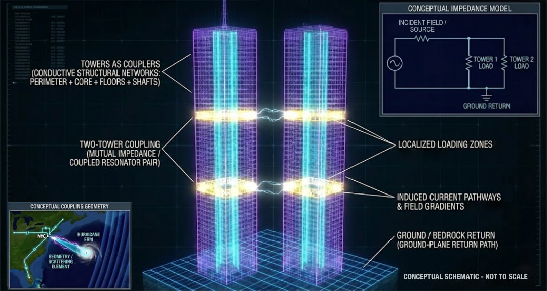
Conceptual schematic: Two-tower coupling.
-
Return Path / Ground: Manhattan bedrock + conductive infrastructure — ground-plane return completing the effective circuit loop. On this reading, slurry-wall survival and subgrade preservation are not residual anomalies; they are expected outcomes if the towers behave as the high-coupling load while true ground components remain the low-impedance reference.
-
Regional HF Emitter (ENE / East-Northeast sector / leading current candidate: BNL): The reconstruction requires a phase-stable HF source in the NYC region capable of supplying a coherent HF carrier at the target (via ground-wave and/or sky-wave propagation) and providing a modulation/clock reference for the interferometric geometry (Phase IV). For engineering concreteness, Brookhaven National Laboratory (BNL) is carried here as the leading current candidate for that ENE-sector role. This is a candidate attribution, not a settled site claim; exact site attribution, operating mode, field-at-target, phase stability, path geometry, and collateral fit still need tightening, but they do not reset the ENE direct-path role to zero. Under ionosonde/TEC null constraints, this source is not required to produce a detectable overhead bulk-heating signature above NYC; if any engineered ionospheric modification occurred, it was below detection thresholds or not of the bulk-heating type those instruments would register (see Bridge Appendix J.9).
- Frequency band: The fringe geometry module derives an HF band of ~2.6–10 MHz under stated assumptions (crossing-angle geometry + WTC feature scales). This overlaps the HAARP operational window (2.8–10 MHz), but the overlap is used as a frequency-range capability check rather than as attribution proof. Full derivation, sensitivity analysis, and uncertainty bounds are in the APPENDIX - Fringe Spacing Geometry Module.
-
Activation Transient (Soft Gate / Onset Handle): A coherent onset of an H-component bay recorded in the GIMA/GIMA-adjacent Alaska chain serves as an exogenous timing handle consistent with the environment entering a changed coupling regime. In commonly shown plots, the first clearly visible deviation appears around ~08:20 EDT (~12:20 UTC). This handle is carried as “soft” (gradual transition; not a step-function) and is not used as calorimetry.
-
Medium (Coupling Pathway): Earth–ionosphere environment — enhanced magnetosphere–ionosphere coupling under HSS forcing (FAC-driven reconfiguration and elevated ionospheric potentials). Ground coupling proceeds through regional electromagnetic induction and lower-boundary pre-bias: time-varying ionospheric currents/fields, atmospheric boundary conditions, and conductive infrastructure establish favorable lower-altitude electrical conditions, including possible GIC-like currents. The effective regional field envelope used in the bridge appendix is an onset-bookkeeping parameter, not a measured crustal geoelectric-field product. The lower-atmosphere bridge is not carried here as unbounded hypothesis space; it is carried as a constrained physical envelope within which localization still has to be more tightly closed. This formulation keeps "FAC" in its established domain (ionosphere/magnetosphere) and does not assume a literal continuous upper-atmosphere-to-ground current conduit.
- Compressed bridge picture: At page level, the bridge is carried as a staged localization-and-capture regime: regional pre-bias and threshold lowering, localized onset near the target, handoff into tower/infrastructure geometry, and then sustainment/sharpening under the tower/load network. Localized ionization / avalanche pockets, corona or streamer activity at elevated conductive boundaries, time-domain loading / storage behavior, and waveguide or impedance-gradient shaping remain candidate local modes within that staged envelope. Exact field strengths, conductivity values, handoff efficiency, and implementation sequencing are routed to the active bridge-validation lanes.
-
Hurricane Erin (stabilizer and shaping medium):
- Observed stabilizer / geometry anchor: Erin is the best-available macro-scale atmospheric geometry for the event window: a stable, long-lived synoptic component whose near-stall provides a fixed Erin-sector arrival geometry.
- Engineering-legible shaping medium: Erin is carried as a refractive/impedance-gradient environment capable of shaping propagation/scattering geometry and maintaining a consistent Erin-sector arrival direction at the target.
- Downstream validation lane: The stronger claim that the Erin-sector path carried the effective high-power broadwave component (Component A) is an implementation-level validation lane rather than something established by the atmospheric observations alone.
- Why stabilization matters: Erin's position affects the scattering/re-radiation geometry, which in turn affects fringe registration on the WTC buildings. Quantitative sensitivity analysis (geometry drift → phase drift) is provided in the APPENDIX - Fringe Spacing Geometry Module. If Erin's effective scattering centroid shifts, the fringe pattern shifts correspondingly.
-
Hardware / Coupling Geometry: The "Invisible Tripod" remains the organizing scaffold for the current reconstruction rather than a separately proven machine. The tripod comprises one ground-based HF source (ENE sector), one stabilized atmospheric propagation/scattering geometry (Erin sector), and one vertical stabilizer (airborne / satellite-class candidate family). The X/Y fringe pattern is produced by bistatic geometry: the direct HF path (Component B) interferes with the Erin-sector path (Component A), creating the horizontal node/anti-node structure. Component C provides vertical pinning.
3. What is already conditionally testable
- Quantitative geometry: the ENE↔Erin geometry implies a specific HF band and a specific fringe orientation.
- Source-sector fit: a serious ENE-sector facility candidate should be testable through archival timing, operating-mode, and collateral checks.
- Bridge collateral envelope: any viable localization path must remain consistent with the ionospheric nulls, expected RF/chemistry signatures, and collateral-containment constraints.
4. Active reconstruction-validation lanes
The current reconstruction path is being tightened through four active validation lanes: lower-atmosphere localization/capture, the FAC-linked HF broadwave contribution (Component A), fringe-contrast / link budget, and control / coherence architecture. These lanes should be read as a staged dependency chain, not as a generic downgrade signal. Some lanes narrow which bridge path is being carried; others quantify the selected path's power, contrast, collateral, and stability margins.
Sharper mechanism deduction can retire broad candidate variants and make the remaining calculations smaller. It does not by itself replace those margin checks, and it does not restore Model A or erase the surfaced mechanism signature. The lanes are stated in full in IMPLEMENTATION VALIDATION LANES below.
QUANTITATIVE GEOMETRY MODULE (Conditional)
This is the reconstruction's clearest falsifiable program and one of its strongest conditionally testable elements. The reconstruction carries two geometric constraints from the APPENDIX - Fringe Spacing Geometry Module. Full derivations, sensitivity analyses, methodological guardrails, and pre-registration requirements are carried in the appendix:
The carried burden is not the mere existence of scale matches. It is the joint conditional package: angle-dependent band placement, an independent bisector-orientation relation, and a pre-registered spatial correlation test that can succeed or fail.
-
Band placement (crossing-angle geometry): If two HF wavefronts arrive at WTC from the ENE-sector bearing and the Erin-sector bearing, the crossing angle implies an HF frequency band (a geometric constraint). The derivation, sensitivity analysis, methodological guardrails, and uncertainty bounds are carried in the appendix.
-
Fringe orientation (bisector geometry): The ENE↔Erin-sector bisector direction is close to the WTC building face orientation, predicting E-W damage boundaries. Statistical significance, multiple-comparison corrections, and pre-registration requirements are detailed in the appendix.
These findings would be falsified in their strongest quantitative form if a pre-registered spatial correlation test — applying the predicted fringe map to independent damage-boundary data — fails to show significant correspondence. That outcome would reject the strongest fringe-map explanation of boundary placement, not automatically erase the weaker band-placement and orientation constraints. The correlation protocol (match metric \(R\) over a pre-registered feature set, null-distribution test, fail-fast criteria) is defined in the appendix.
Validation lane: Band-placement and orientation observations are reported. The companion spatial-analysis bundle is the active validation lane for the stronger map-level claim: whether a computed fringe/node map fits independent damage-boundary data better than chance.
PHASE I: GUIDANCE & POSITIONING (The "Setup")
Time: Overnight 09/10
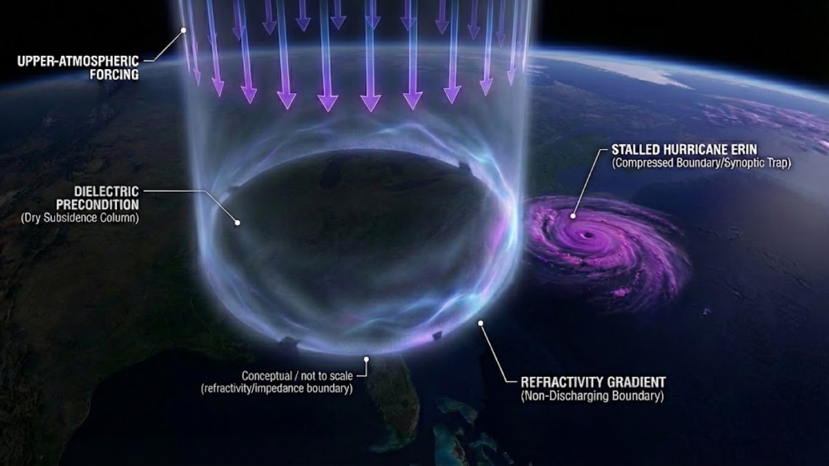
Status: GEOMETRY STABILIZATION / DIELECTRIC PRECONDITION
The Requirement
To utilize the incoming forcing context in a bounded, time-gated way, the current reconstruction carries two setup conditions:
- A stationary / stabilized sector geometry (the near-stalled storm) to serve as an anchoring atmospheric component and fixed element of the bistatic geometry.
- A dielectric precondition (severe-clear over the target) to reduce premature discharge and preserve a controllable local environment.
The Role of the Regional HF Emitter (Carrier/Clock + Source-Sector Anchor)
In this reconstruction, the regional HF emitter is carried as the later phase-stable carrier/clock reference for interferometric geometry (Phase IV) and as the ENE-sector source anchor used in the geometry bookkeeping. It is not required to produce a detectable overhead bulk-heating signature above NYC (see Bridge Appendix J.9). The Phase I severe-clear / subsidence and Erin near-stall are observed prerequisites; attribution to a specific preconditioning or upper-atmospheric forcing mechanism remains a separate architecture question.
- Functional Requirement: The SCIE mechanism requires a temporally stable lower-atmosphere dielectric state over NYC (sharp subsidence inversion / severe-clear). This condition suppresses uncontrolled discharge pathways and stabilizes the coupling geometry during the charging interval.
- Observed Condition: Radiosonde and surface data on 2001-09-11 show a sharp subsidence inversion consistent with a strong ridge and subsidence, providing the exact dielectric environment required by the reconstruction.
- Attribution burden: The reconstruction carries this state as a machine prerequisite. Whether it arose through a bounded synoptic-only evolution that still leaves the event-window alignment incidental, or through an additional forcing mechanism, is a separate architecture question. Even if meteorologically plausible, the co-occurrence of a strongly stabilized dielectric state with the event window remains a forensic flag that warrants targeted investigation rather than being treated as accidental geometric convenience.
- Result (Geometry Lock): By stalling Erin (or utilizing its stall), the system keeps the ENE↔Erin-sector↔WTC triangle stable throughout the event window, holding fringe registration within bounded drift (see sensitivity analysis in the APPENDIX - Fringe Spacing Geometry Module).
Summary of Phase I: The setup is in place: Erin provides a stable sector anchor, and severe-clear conditions reduce uncontrolled pre-discharge pathways while the event window approaches.
Phase 1.
PHASE II: CONNECTION / LOCAL ACTIVATION WINDOW (SOFT ONSET)
Time: 07:00 AM – ~08:20 AM (EDT)
Status: FORCING CONTEXT / EARLY REGIME ENTRY
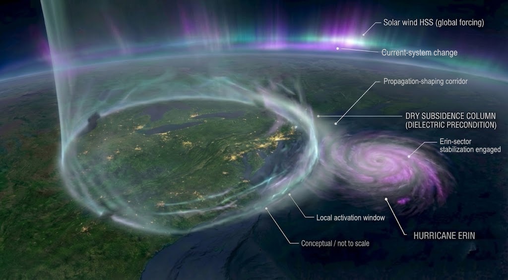
- Power Source (07:00 AM): The leading edge of the solar-wind HSS initiates the global-scale forcing context (~11:00 UTC / 07:00 EDT) for enhanced regional coupling. The HSS functions as an external driver/reservoir context (forcing regime), not as a site-specific energy source. Accordingly, the ~11:00 UTC timestamp is used as the onset of forcing availability (entry into an HSS regime).
- Onset handle (~08:20 AM): In commonly shown plots, the Alaska magnetometer chain shows the first clearly visible onset of a coherent H-bay around ~08:20 EDT. This serves as an exogenous timing handle for a current-system change and a useful local activation marker within the reconstruction. It is not a substorm onset, not a sharp switch, and does not need to represent a unique system start time. It is used for sequence bracketing only.
Interpretation: Because the Phase I conditions are already in place, the incoming forcing context can be carried as organized loading rather than as diffuse convective discharge. The magnetometer onset provides a soft activation marker for sequence bracketing, but the reconstruction does not require a unique "gate opens" instant, nor does it claim that a full expansion-phase coupling regime was already operating. Even so, this phase is still carried as the beginning of an activated local reconstruction path, not as a mere background precondition. The coupling pathway remains enhanced magnetosphere–ionosphere coupling (FAC/ionospheric potential/current-system changes), with ground coupling treated via induction plus a localized atmospheric bridge within the constrained envelope described above. Larger-scale loading can continue beyond this interval.
Phase 2
PHASE III: LOADING (The "Lead Time")
Time: ~08:20 AM – 08:46 AM
Status: LOCAL LOADING / EARLY GROWTH-PHASE PREPARATION
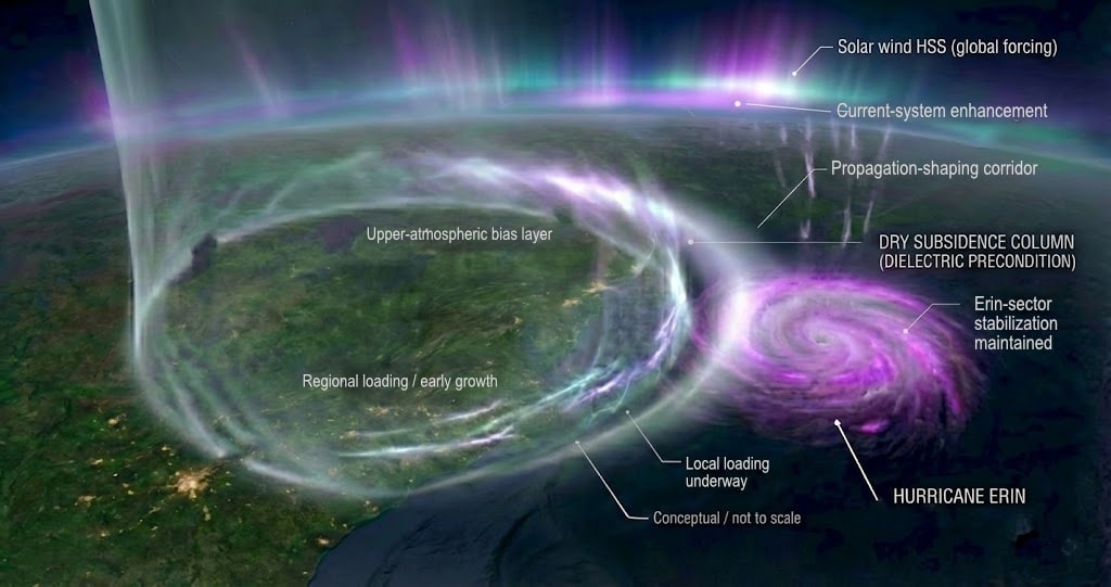
- The Delay (τ): \(\tau\) is a coarse pre-impact lead-time bracket (on the scale of ~half an hour), not a precisely measured constant. For sequence bookkeeping it is bracketed from the onset handle (~08:20) through 08:46. In the current reconstruction, this interval is best read as the first segment of a longer growth phase rather than as the entire reservoir-loading history.
- The Physics (current leading picture): The stabilized atmospheric component (Erin) and the ground/node environment over Lower Manhattan form a coupled time-domain loading regime. Capacitive language is used here as an analogy for storage/charging behavior during ~08:20–08:46, while Erin's boundary-condition shaping (ducting/refraction/impedance gradients) supplies the primary way local coupling efficiency and localization are enhanced without requiring bulk overhead heating signatures.
- Atlantic / Erin-sector contribution (Component A status): The current reconstruction path does not require the later FAC-amplified Atlantic contribution to have reached its eventual peak strength by 08:46. It requires only that an Erin-sector companion path or shaping contribution already be present and that regional forcing be moving into a more favorable loading state. This focuses the active Component A validation lane: how large the pre-substorm contribution was, and how it evolved into the mature-phase field-ratio burden.
- Towers as Charging Electrodes (Field Enhancement): During this interval, the Towers are carried as elevated conductive electrodes that concentrate field intensity and gradients (edge/tip enhancement), lowering the effective threshold for localized ionization pockets, corona-like effects, EMI susceptibility, and pre-kinetic emission phenotypes where claimed. This is the bridge from regional loading conditions to local node viability.
- The Evidence: Reports of "clear-air thunder," "greyout," and static/EMI anomalies indicate that the medium may have been approaching saturation-like conditions prior to the main load interval. Their diagnostic role is timing/sequence consistency within the reconstruction, not standalone proof of the final link budget.
Phase 3
PHASE III → PHASE IV:
At ~08:46 EDT (end of the τ loading interval), the model transitions from preparatory loading (Phase III) into the onset of a coherence-controlled regime (Phase IV). On the current reconstruction path, this does not require the later FAC-amplified Atlantic contribution to have already reached its eventual peak amplitude. It requires that the ENE direct path be active, that an Erin-sector companion path or shaping contribution already be present, and that the tower/ground geometry already support bounded localization plus first-stage capture into the elevated conductive load. Phase IV onset is therefore carried here as an event-stage transition within an already-activated coupling regime. The stronger link-budget claim that Components A and B achieve the field ratio needed for high-contrast node/anti-node boundaries is formalized in the APPENDIX - Bridge Mechanism Physics as an implementation-level validation lane. If both fields share a common HF carrier/clock reference, their superposition can still produce a bounded interference structure that sharpens as the regime strengthens. This transition therefore represents an impedance/geometry reconfiguration within an already-prepared coupling regime, not the onset of a new energy source.
PHASE IV: THE EVENT (Active Interferometry & Discharge)
Time: 08:46 AM – 10:28 AM
Status: TARGET AEROSOLIZATION / ATHERMAL PLASTICITY / NODE-BOUND COUPLING
1. Activation (The "Invisible Tripod")
The named components below are carried as current path roles within the reconstruction. Their engineering roles are more settled here than their exact site/platform attribution.
At 08:46 AM, the first impact marks the onset of the main load interval within the reconstructed coupling regime. In this reconstruction, the impact functions as an impedance perturbation / transient gating disturbance (geometry alteration, conductive-path modification, local arcing/ionization, or gating disturbance) coinciding with the transition from charging to active discharge, functioning as a trigger within the already-driven system rather than as the primary energy source. The precision of the destruction—nodes of dissociation adjacent to anti-nodes of relative survival—requires a multi-vector interferometric geometry.
Node boundaries are thresholded: destructive coupling occurs primarily where field intensity/gradients exceed coupling thresholds within bounded volumes, producing sharp on/off spatial transitions consistent with the dossier's geometric constraint claims.
This section therefore carries an event-stage reconstruction, not merely a menu of possible subsystems. The active validation work at this stage concerns amplitude, attribution, and control margins within that architecture.
Component A (The "Anvil" — Atlantic Broadwave)
This is carried here as the Atlantic/Erin-sector companion field within the current SCIE reconstruction: the HSS-enhanced magnetosphere–ionosphere forcing (FAC/ionospheric potential structure) expressed at the target as a coherent carrier field arriving from the Erin/Atlantic sector. It is not an independent transmitter; the bulk energy is attributed to the HSS-driven current system, while the coherence/modulation pattern is attributed to the regional HF source acting through the Erin-shaped propagation/scattering geometry. Its exact amplitude history across the event window is routed to the Component A validation lane, especially in the pre-substorm interval.
This identification is the current leading implementation choice: it trades a "mystery transmitter" for a testable coupling claim, but FAC/HSS energy must still be shown capable of producing an HF-band re-radiated field at the required amplitude and phase stability (see Bridge Mechanism Physics Appendix).
The current reconstruction therefore does not require identical Atlantic contribution across the whole 08:46–10:28 window: Tower 2 is carried under weaker growth-phase conditions, while Tower 1 overlaps the later geomagnetic intensification.
- Source: The HSS-driven FAC current system (global potential).
- Modulation: A regional HF source supplies a phase-stable HF carrier (2.6–10 MHz band per the geometry module) used as the modulation/clock reference for the architecture.
- Channeling: The HSS-enhanced currents flowing through this modulated channel re-radiate or "leak" the modulation pattern as a coherent field.
- Geometry: The effective source appearing at WTC is the re-radiating ionospheric volume to the SSE (~149.7° bearing), shaped by the Erin-associated stabilized geometry carried in the reconstruction. Qualifier: The ~149.7° SSE direction is an Erin-sector proxy; the physically relevant effective source can be an aloft centroid offset by Δθ — treat as bounded uncertainty unless independently constrained.
-
Phase Coherence: Inherently coherent with the regional HF source because it provides the modulation/clock reference.
-
Forensic Support: Consistent with line-of-sight boundary behavior and aperture/occlusion-style constraints observed in collateral structures. The fringe orientation (114.5° bisector) predicts E-W damage boundaries — matching WTC 4 knife-edge and WTC 3 bisection observations (see Fringe Appendix 8.2 in the Fringe Spacing Geometry Module).
Component B (The "Shear" — HF Direct Path, ENE sector)
The HF carrier arrives at WTC via direct ground-wave or near-ground propagation from the ENE sector (~79.3° bearing), carrying the modulating interference component that shapes localization and boundary sharpness in X/Y. At WTC, this signal interferes with Component A (arriving from ~149.7°), producing the fringe/node pattern.
- Geographic Profile: The ENE proxy bearing (~79.3°) is consistent with a regional ground-wave/near-ground path at 2.6–10 MHz over a mixed land/coastal corridor. Within the current reconstruction, this direct path is the more concrete of the two X/Y sources, and BNL is carried upstream as the leading current facility candidate for it. Exact site attribution remains downstream specification work, but the direct-path role itself is not treated here as optional.
Component C (The "Hammer" — Vertical Pinning)
A vertical pinning component (E-4B/satellite-class candidates) acts as the Z-axis stabilizer and guidance/pinning vector. It does not supply bulk energy; it constrains node geometry and containment along the vertical axis so that coupling tracks down the conductive structure rather than dispersing. This role is already carried as an engineering-legible part of the current reconstruction; exact platform identity and PLL specification remain downstream attribution/specification tasks, not the need for a vertical stabilizing function itself. Component C requires separate phase-locking to the HF reference via GPS-disciplined or atomic timebase (a standard engineering requirement; far simpler than locking three fully independent sources). Platform identity and PLL specifications remain downstream specification tasks rather than one of the four core validation lanes.
Phase Coherence: The phase coherence of the X/Y fringe pattern (Components A and B) is inherent if both paths share a common HF carrier/clock reference. The direct path (B) and the FAC-re-radiated path (A) are automatically phase-coherent if they are derived from the same regional HF source. The fringe pattern's stability depends on:
- Maintaining a stable CW HF carrier (standard engineering requirement for high-stability transmitters)
- Erin remaining positionally stable (an observed synoptic condition in the event window)
- The ionospheric propagation/scattering geometry remaining stable over the load interval (an implementation burden not assumed to be maintained by detectable bulk heating)
"Standing-wave" language is used here as shorthand for waveguide/boundary-condition effects (conductive ground, the Earth–ionosphere waveguide, and transient atmospheric refractivity/ionization associated with the stabilized atmospheric component) that can shape mode structure and focusing. As a quantitative check on boundary placement (regardless of whether coherence is achieved passively via mode structure or actively via control), see: APPENDIX - Fringe Spacing Geometry Module.
2. Grounding (Circuit Return / Slurry Wall Constraint)
The interferometric geometry provides bounded coupling, but the ground plane provides the return path.
- Mechanism (Circuit Flow Model): Magnetosphere–ionosphere forcing → FAC re-radiation + ENE-sector HF direct path → structural impedance network (towers) → ground plane return.
- Functional role: The Towers act as the dominant impedance/load element (elevated electrode/monopole coupler) between the regional potential environment and the ground return, concentrating work in the load rather than uniformly in the ground reference.
- Slurry Wall Constraint: The survival of the bathtub wall represents a selective-coupling boundary condition: true ground components in wet soil remain low-impedance ground reference, while the towers behave as a high-coupling impedance network under node conditions.
- Payoff: On this reading, slurry-wall survival and subgrade preservation are not residual anomalies; they are expected boundary outcomes if work is concentrated in the towers rather than expressed as a dense ground-coupled termination.
- Rule of the Circuit: Energy preferentially loads the impedance structure under coupling, not the ground reference—consistent with "current destroys the resistor, not the ground wire."
3. Pre-Collapse Phenomena (Pre-kinetic Aerosol Emission & Athermal Plasticity)
Prior to final termination, the reconstruction includes:
- Pre-kinetic aerosol emission ("fuming"): Not smoke; ionization/aerosol emission consistent with IMD-mode dissociation products and material-selective coupling.
- Athermal Plasticity (Blaha Effect regime): Low-frequency vibration ($(t > 30s) $) represents dislocation unpinning, reducing yield strength and enabling non-standard deformation (curling/rolling rather than classic buckling).
These are carried here as event-stage payoffs of an already-active regime, not as isolated curiosities that wait on later reconstruction closure to become meaningful.
4. The Discharge (Rapid Macroscopic Aerosolization)
During the load interval the towers act as a strong-coupling impedance network (monopole-like conductive geometry). Under node conditions:
- Conductor-regime routing (default): In this reconstruction, side-lobe/node denotes thresholded constructive vs weakly coupled regions (interferometric intensity/gradient modulation), while the conductor response is conductive-loop coupling (CLC): induced currents with downstream Joule heating ($(P=I^2R) $) and frequency-dependent skin-effect gradients. This routing produces selective impedance heating (SIH) phenotypes in secondary targets (vehicles, PPE loops, handles) where claimed; ECR-regime coupling is reserved for cases where resonance-specific conditions (field + magnetization + geometry) are argued rather than assumed.
- ECR-regime coupling (conductors): Rapid internal heating/oxidation and conductive-loop targeting occur without requiring environmental bulk heating.
- IMD (bond scission) + Coulomb Explosion (dielectric saturation): Drive rapid macroscopic aerosolization of structural and contents mass, producing fine/ultrafine particulate modes observed in the dust record.
- Volumetric Mass Deficit: The absence of a conventional rubble phase is explained as phase conversion plus export (aerosol dispersal), not as simple stacking.
Phase 4.
Phase 4.5.
PHASE V: BIO-KINEMATIC & COLLATERAL ANOMALIES
Status: DEP BODY-FORCE EFFECTS / INTERFEROMETRIC SIDE-LOBES (CLC/SIH in conductive loops; ECR where resonance-specific conditions are argued)
1. Collateral Geometry (Occlusion / Aperture Evidence)
Collateral building damage patterns support bounded coupling and line-of-sight constraints:
- WTC 4 (Knife-edge survival): A surviving wing consistent with occlusion/aperture shielding effects. The knife-edge boundary divides the building into destroyed (south) and intact (north) portions. This orientation is consistent with the predicted fringe direction (see Quantitative Geometry Module and fringe appendix for details and caveats).
- WTC 3 (Bisection / core negation): Destruction strip running along the E-W building axis, consistent with a fringe node line at the same orientation. Geometric subtraction inconsistent with random debris impact.
- WTC 6 (void / aperture complex): Scalloped vertical void geometry consistent with collimated node/side-lobe geometry rather than stochastic crush. Its principal dark-core / sub-aperture lateral scale has no preferred orientation — consistent with any fringe direction.
- These are candidate calibration targets for a quantitative interference-geometry map test; see: APPENDIX - Fringe Spacing Geometry Module.
2. Bio-Kinematic Anomalies (Field Repulsion / Heating)
- Jumpers (Field Ejection): Horizontal ejection distances/initial vectors inconsistent with biomechanics alone; DEP body-force effects acting on polarizable biological mass in high-gradient fields.
- Disrobing: Modeled as RF dielectric heating—moisture-coupled volumetric heating in damp clothing producing "boiling bandage" behavior distinct from fire shielding.
- Dry Severance: Reports of reduced hemorrhagic infiltration are consistent with pre-impact thermodynamic alteration (field-mediated coagulation/flash effects) rather than purely post-impact mechanics.
3. Side-Lobe Signatures
- Toasted Cars: Remote vehicle internal heating/oxidation consistent with side-lobe/node conductive-loop coupling (CLC) producing SIH phenotypes, with selective sparing of low-loss dielectrics nearby (ECR-regime coupling is reserved for resonance-specific claims where argued rather than assumed).
- Vehicle Displacement: Flips/lateral lifts modeled primarily as DEP / field-gradient body-force effects (and conductive-loop coupling where relevant), rather than wind or blast.
- Athermal Fusion Artifacts: Composite "meteorites" consistent with athermal interfacial sintering / lattice intercalation signatures (phase interaction without bulk thermal history).
Phase 5. Conceptual visualization only.
PHASE VI: SYSTEM RELAXATION (Site Load Loss within Broader Geomagnetic Expansion)
Time: 10:28 AM – ~02:00 PM
Status: SITE LOAD LOSS / BROADER GEOMAGNETIC RELAXATION
-
Context: The Inter-Collapse Surge (10:00–10:28 AM)
Magnetometer data (Alaska chain) shows a sharp "electrojet strengthening" or high-conductance surge through the window between the collapses. In the current reconstruction, this is no longer treated as having been caused by Tower 2's collapse. It is carried first as the broader geomagnetic intensification that overlaps the inter-collapse interval, and only secondarily as part of the timing context within which the site-level architecture may have been operating. -
Final Load Shedding (~10:28 AM)
By ~10:28 AM, the destruction of the North Tower removes the final primary electrode. That is the decisive site-level load-loss event in the reconstruction: the HF coupling geometry loses its strong coupling target because the impedance network is destroyed. This site transition remains meaningful even though the wider geomagnetic system continues to evolve on its own timescale. -
Geomagnetic / Magnetometer Recovery
Following the 10:28 AM collapse, the intensified negative bay observed in the traces (specifically Bettles/66°N) continues to evolve, peaking shortly afterward and then relaxing/recovering. Phase VI carries this primarily as geomagnetic context overlapping the end of the site event rather than as proof that the towers themselves drove electrojet decay. -
Post-10:28 relaxation / latitude structure (Poleward Expansion):
After ~10:28, the intensified bay at Bettles (66°N) relaxes, while Kaktovik (70°N) shows a later dip consistent with latitude-dependent electrojet evolution (often described as poleward expansion during relaxation). This broader reconfiguration timeline is compatible with the release/relaxation sequence carried in the reconstruction, but it is not presented as a SCIE-unique signature. Its role here is environmental bracketing, not site-specific calorimetry. -
Atmospheric Hysteresis (The Component)
Simultaneously, the atmospheric component (Hurricane Erin) exhibits inertial hysteresis. Rather than accelerating away immediately, NHC data confirms the storm decelerated to ~6 MPH and executed a slow pivot to the Northeast during this afternoon window. This "lag" is compatible with synoptic steering dynamics; any additional electrodynamic contribution is mechanism-dependent and is not assumed here. This also brackets the end of Erin's carried role as scattering geometry in the reconstruction.
Phase 6.
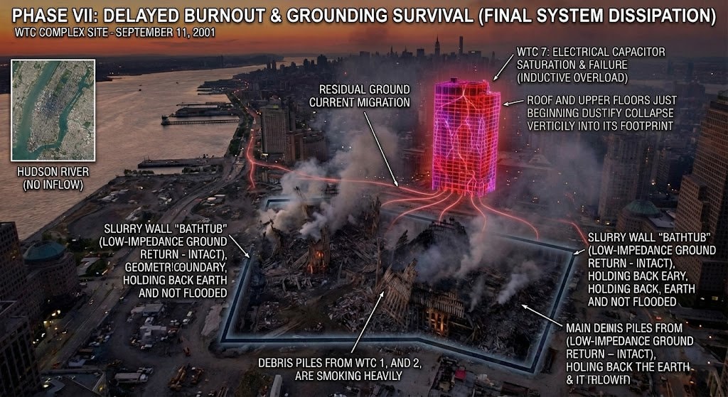
PHASE VII: THE AFTERMATH (Seismic Constraint & WTC 7)
Status: SUPPRESSED GROUND-COUPLED IMPULSE / HYSTERESIS & DELAYED TERMINATION
The Seismic Constraint (Ground-Coupled Impulse Gap)
A collapse of this scale implies large potential energy release. In a conventional gravity termination, a significant fraction couples to ground as impulse and seismic energy.
- Observed: (M \sim 2.3) (WTC1/2) rather than expected higher coupling for intact macroscopic mass; (M \sim 0.6) for WTC7. The 0.6 value is recoverable directly from Lamont's archived WTC event-summary table; see SCIE Reconstruction Data Sources.
- Deduction: The seismic constraint limits ground-coupled impulse/energy transfer, implying substantial pre-impact aerosolization/momentum decoupling and non-standard termination mechanics under SCIE conditions.
- Conclusion: The key inference is not "mass went to zero," but that effective ground-coupled impact momentum was greatly suppressed—consistent with pre-impact phase conversion and dispersal.
WTC 7 (Delayed Termination under Side-Lobe Exposure)
- Time: 05:21 PM.
- Mechanism (Reconstruction Model): WTC 7 functions as a secondary structure exposed to prolonged side-lobe conditions: cumulative lattice fatigue, pre-kinetic aerosol emission, and ionization/IMD hysteresis effects.
- Termination: The structure ultimately fails with low ground-coupled signature relative to conventional impact expectations, consistent with delayed SCIE-mode weakening rather than a pure gravity-driven collision termination.
Phase 7.
IMPLEMENTATION VALIDATION LANES
The following items are the main implementation-level validation lanes within the current reconstruction path. They do not erase the surfaced mechanism signature, and they do not, by themselves, repair Model A.
Read this list as path-narrowing plus selected-path parameter validation: the bridge and Component A lanes tighten which implementation path is being carried, while the link/contrast and coherence lanes quantify whether that selected path has enough margin under stated assumptions. That is implementation tightening, not a reset to zero.
- FAC-linked HF broadwave contribution (Component A): The Atlantic/Erin-sector companion field is already carried in the current reconstruction path; the active task is tighter theoretical and observational parameterization of its 2.6–10 MHz contribution, especially in the pre-substorm interval. Minimum verification requirements and expected ancillary signatures are specified in Bridge Appendix J.8.
- Fringe-contrast / link budget: The broadwave component must reach WTC at sufficient amplitude relative to the direct HF path to support at least onset/localization and, for the stronger version of the reconstruction, the later sharpest node/anti-node boundaries. The required field ratio and the distinction between onset-phase and mature-phase thresholds are formalized in Bridge Appendix J.7.
- Lower-atmosphere localization / capture: The bridge is already carried as a constrained physical envelope rather than an open guess; the active task is tighter parameterization of the staged localization/capture path connecting the ionospheric environment to the WTC target volume within that bounded envelope. Candidate mechanisms and their predicted collateral signatures are outlined in Bridge Appendix A–D.
- Control / coherence architecture: Bounded node geometry already carries a real stability requirement; the active task is tighter parameterization of how coherence and timing stability are maintained under real propagation-path drift and event-window changes.
FINAL DETERMINATION
The integrated timeline—regional charging onset, bounded node geometry, selective coupling signatures (CLC/SIH by default in conductive pathways, ECR where resonance-specific conditions are argued, plus IMD/Coulomb/DEP effects), suppressed ground-coupled impulse, and coherent collateral geometry—supports the reconstructed classification within the dossier's audit framework and constraint stack:
SCIE (Reconstructed Classification Supported): Spatially-Constrained Interferometric Event — Time-Domain Interferometry + Regional Circuit Discharge.